Activity diagrams can also implement logic that is based on conditions. You can branch a control flow using the Decision element.
The following example shows how to use decisions in activity diagrams. The user can enter a positive number. The process will then return a message depending on if the number is smaller or greater than 10 and divisible by 4.

The branching conditions of the decision must evaluate to a Boolean value (boolean expression) and be defined on the outgoing control flows of the decision node as a Guard Expression. Page Logical Operators provides a list of all possible logical operators that can be used within a guard expression. You can also use Boolean operators (and, or) as described in Boolean Operators.
In the example above, there are three outgoing control flows:
|
Nr. |
Control Flow |
Condition |
Guard Expression |
|---|---|---|---|
|
(1) |
Decision → smallerTen |
entered number smaller than ten |
|
|
(2) |
Decision → divisibleByFour |
entered number divisible by four |
|
|
(3) |
Decision → greaterEqualTen |
all other cases |
|
The one or more of the control flows contain the actual condition(s) ((1) and (2)). Exactly one control flow must contain an else expression (3): This control flow is followed if all other expressions evaluate to false.
The boolean operators of the xUML Runtime support short-circuiting . This means that the second operand is evaluated only when the result is not fully determined by the first operand.
Adding a Guard Expression
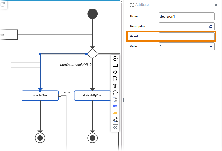
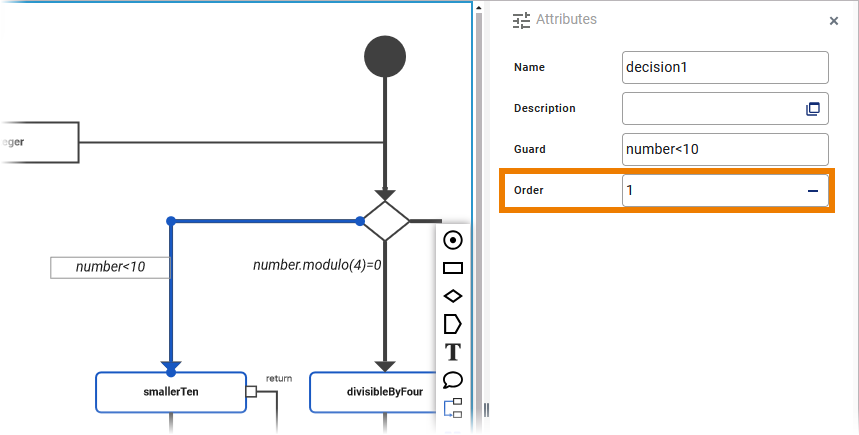
To add a guard expression to a control flow proceed as follows. Select the control flow you want to add a guard expression to from the activity diagram and open the Attributes panel:
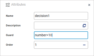
Enter a boolean expression into the field Guard Expression:
The entered expression is also displayed in a box next to the corresponding control flow in the diagram:
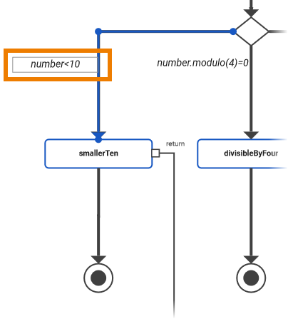
When the guard expression box is selected, you can move it any time. Click the box and drag it to the desired position:

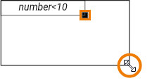
You can resize the guard expression box by clicking the square in the bottom right corner of the element and dragging it:
Specifying an Evaluation Order
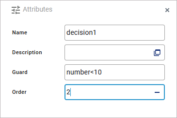
The order attribute on the decision flow defines the order in which the guards should be evaluated. To add an order to a control flow proceed as follows. Select the control flow you want to add an order to from the activity diagram and open the Attributes panel:
Enter the order number you want to assign to the selected control flow:
Examples
The following tables shows some examples regarding the activity diagram above:
|
Example |
Entered Number |
Guard Expression |
Condition |
Result |
|---|---|---|---|---|
|
1 |
7 |
|
|
Branch 1 is followed without evaluating the other two branches |
|
2 |
12 |
|
|
Branch 2 is followed without evaluating the third branch |
|
|
|
|||
|
3 |
14 |
|
|
Branch 3 is followed |
|
|
|
|||
|
|
|
Activity_Decision_Example
Click here to download a simple example model that shows how to use decisions in activity diagrams with Scheer PAS Designer.