
The PAS components are designed to support the entire lifecycle of a business process application: From Development through Deployment, Execution, and Administration to Analysis. Each phase builds on the previous one: processes are modeled and compiled in the Designer, deployed as executable services, managed through the Administration tools, and continuously monitored and optimized using the Analysis tools. This end-to-end lifecycle ensures that business process models don't remain static documentation but evolve into running, governed, and measurable applications.
Development
In development, we distinguish between process and execution modeling. Both are carried out in the Designer, but with different modeling languages. Additional options such as diagrams or coding are also available to bring your process to life.
Process Modeling
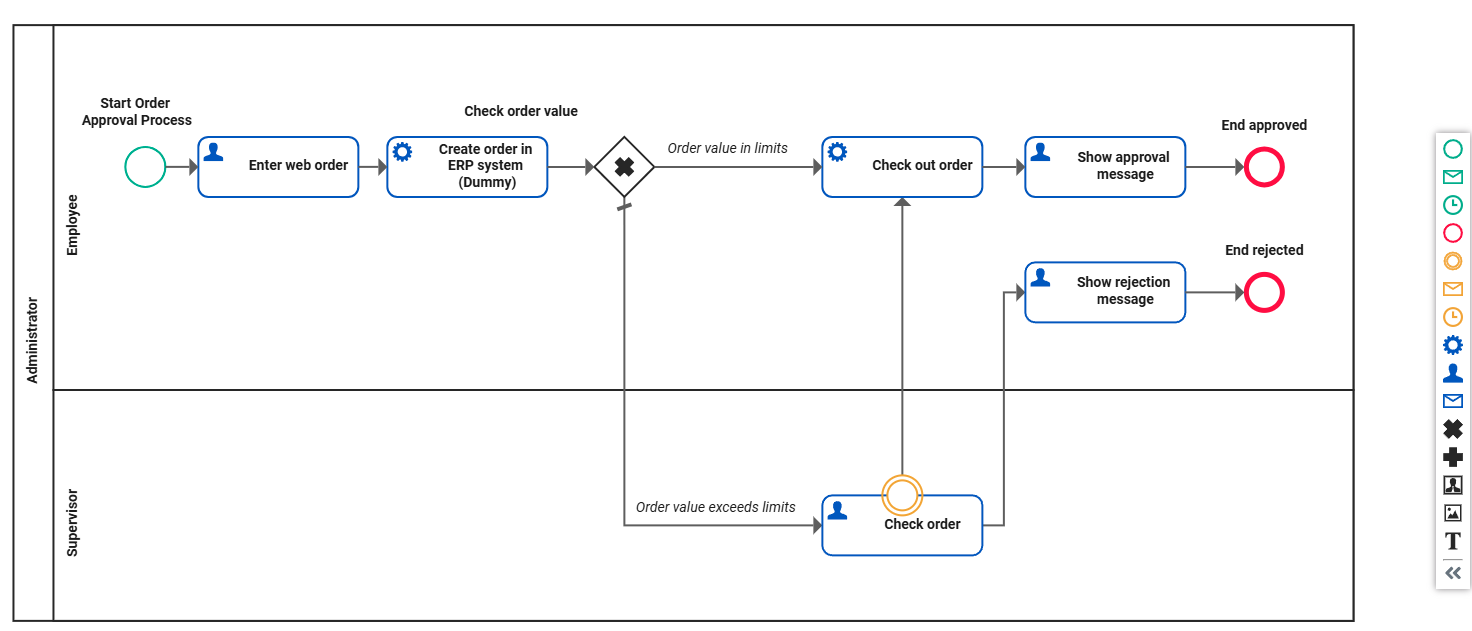
The basic process flow is modeled using the BPMN notation in the BPMN editor of the Designer (refer to Modeling BPMN in the Designer Guide). This includes roles, user-based and service-based tasks, gateways for condition checks, start and end events. Integrations and information flows are realized in a different way. The rough process flow should be known at this point in order to transfer it into a process model.
Business Process Model Notation (BPMN)
The Designer uses a simplified BPMN standard to help users unfamiliar with BPMN notation start modeling. BPMN modeling focuses on process flow.
Execution Modeling
To implement integrations, developer can use UML diagram variants, mapping diagrams, but also programming languages such as Action Script, JavaScript, Java, and Angular.
Unified Modeling Language (UML)
UML offers standard notation for several types of diagrams. Behavioral diagrams, such as activity, sequence, and state diagrams, are particularly used in PAS, especially within the Designer.
Activity Diagram
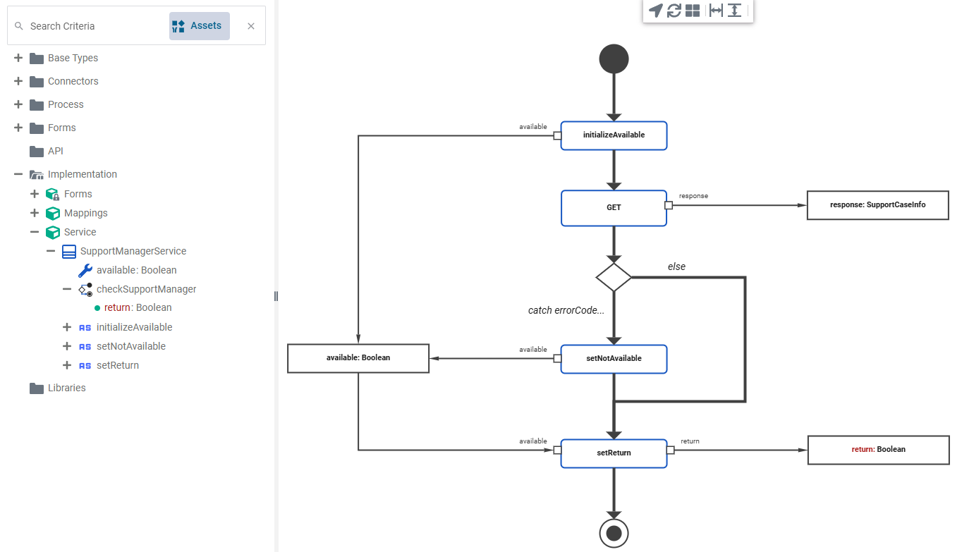
The activity diagram editor, found in class operations, is used to define class behavior (refer to Modeling Activities in the Designer Guide). Activity diagrams are a sub-area of UML. They are an important part of integrations, therefore the Designer has its own editor for creating and customizing activity diagrams. Operations or sub-operations can be created step-by-step. By using decisions, local variables, and more, you can implement complex behavior.
Mapping Diagram
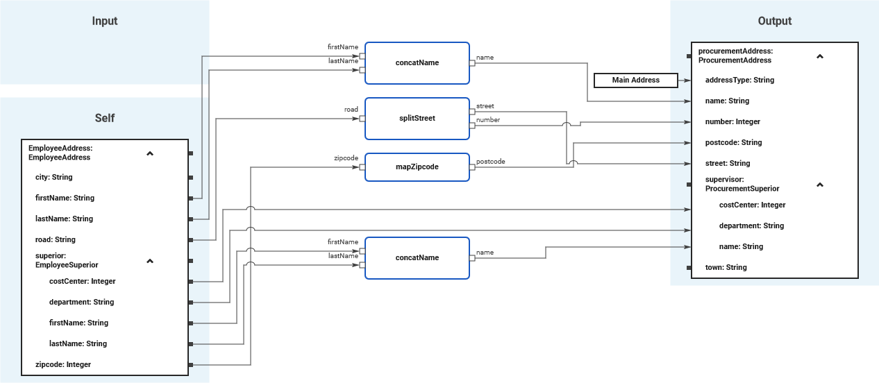
Data mapping is a very common task in the integration business. With the mapping diagram, the Designer offers a powerful tool to define data mappings directly by drawing object flows between the properties of the related classes (refer to Modeling Data Mapping in the Designer Guide). The mapping diagram is based on the data model of the service. It defines mappings between the data structures defined in this data model.
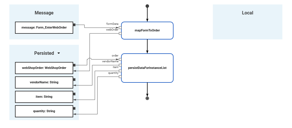
Both activity and mapping diagrams can be integrated in the execution flow (a sequence diagram) to be executed in the subsequently compiled and deployed service (refer to Modeling Execution in the Designer Guide).
In addition to its use in Designer, UML is also used in background processes. Each xUML process modeled with the Designer contains a standard root state machine diagram that supports
error handling and compensation as well as history states. The Analyzer (see below) uses these diagrams to visualize imported xUML processes.
Coding
In some cases, graphical modeling or mapping tools reach their limits. For this reason, it is also possible to create Action Script and JavaScript operations in the Designer. Once you have written the relevant code in the operation editor, you can integrate the operation in the appropriate Designer diagram.
-
Action Script: The Designer offers an Action Script Language that implements the action semantics defined by the OMG™ for the UML. You can implement atomic actions like manipulating strings, arrays and so on by using Action Script. Expressions of the Action Script language are not only used in actions but also for decisions (on the outgoing process flow) to evaluate boolean expressions. For details refer to Using Action Script in the Designer Guide.
-
JavaScript: As an alternative to the built-in Action Script, a JavaScript implementation is also available in the Designer. This allows JavaScript operations to be used to effectively write the function body of a (synchronous) JavaScript function. For details refer to Using JavaScript in the Designer Guide.
Pro-Code Development
When the Designer's editors and diagrams reach their limits, developers can export a service and extend it using the Pro-Code development kit.
Prerequisite: Compilation
The prerequisite for Pro-Code development is the successful compilation of the service. During this process, the xUML compiler transforms models, diagrams, and code into executable xUML services that can then be deployed. Throughout the compilation process, the syntax is checked, and a repository file is created, optimized for size and performance. Additionally, the WSDL file is generated, which describes the service in the Web Service Definition Language. The WSDL file can later be imported into the PAS Analyzer for debugging purposes. All files are stored in a JAR file, that can be loaded by the xUML Runtime (refer to xUML Runtime Architecture and Transaction Concept in the Designer Guide).
The focus of Pro-Code development is primarily on further developments for the service UI and its functions. But developers can also realize user-defined libraries and custom Note.js services with Pro-Code. Programming and markup languages used for Pro-Code development are JavaScript, Typescript, Angular, Java, HTML, and CSS.
The Designer offers several options for extending Designer services with user-defined implementations. Different programming languages are used depending on which customizations are made. Refer to Pro-Code Development in the Designer Guide for further details.
Compilation & Deployment
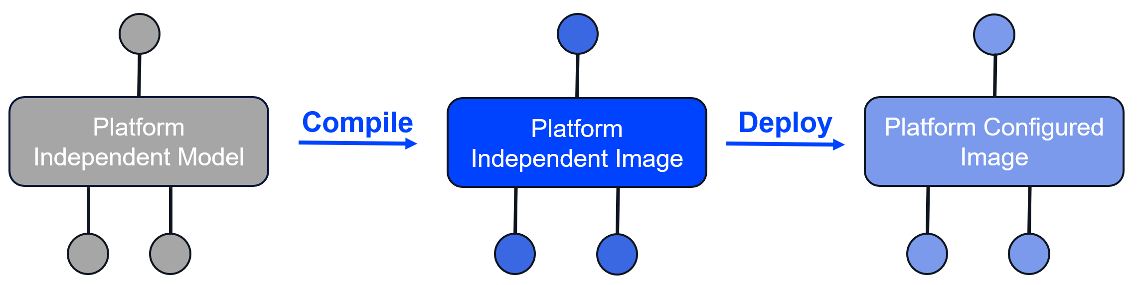
The Compiler converts a Designer service to a repository file. During the modeling process, continuous validation and compilation run in the background to identify potential problems and update the integrated test environment.
Users can start the deployment of the image directly in the Designer or in the service administration. Depending on your Scheer PAS setup, the image is deployed into a Docker container or Kubernetes workload.
-
Docker compose setup: The containers are handled on a single server.
-
Kubernetes setup: You have a provisioned cluster including modularized PAS components running. Internal service communication is encrypted via mutual TLS.
The Runtime assembles the platform-independent image with settings and parameters and transforms it into a platform-configured image. This image can then be deployed directly via the Designer or via the service administration on a Docker or Kubernetes setup.
Developers and administrators can manage deployed services in the PAS Administration (see below).
Process Execution
After successful deployment, the container is started automatically. You can start a service in various ways:
-
For UI-based services, a URL is generated that users can use to execute the application. The URL is stored both in the service administration and directly in the Designer. It starts the service via a generated Angular UI interface.
-
For non-UI-based services, timed events or API endpoints can be used to start the service.
xUML Runtime
The xUML Runtime executes the repository provided by the Compiler. During execution, persistent state management ensures the storage of data objects and state machines preserve the states during asynchronous communication (refer to xUML Service State Machines in the Designer Guide):
-
Synchronous execution relates to the process flow, following the sequence defined in the BPMN editor.
-
Asynchronous execution involves communication with interfaces via adapters and connectors, which are modeled during integration and executed within the execution flow.
The xUML Runtime is comparable to other virtual machines, such as Node or JVM, as it executes code that was previously defined by the user (refer to xUML Runtime Architecture and Transaction Concept in the Designer Guide).
-
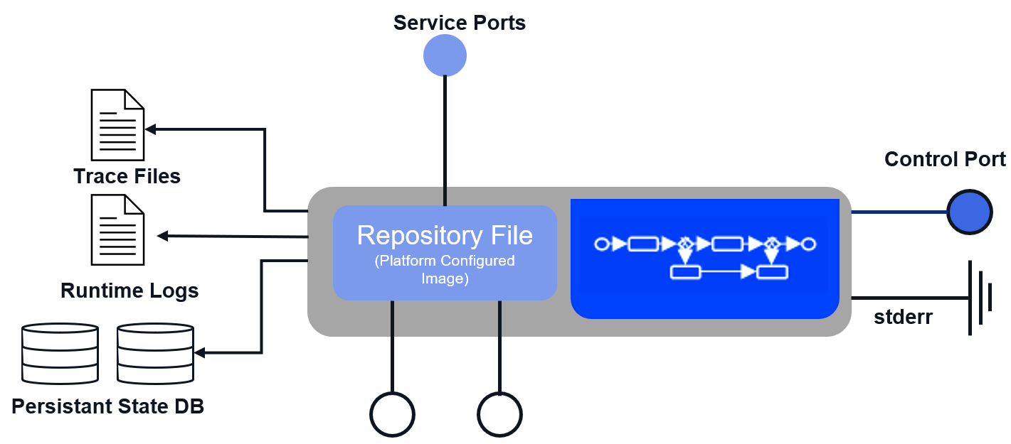
The xUML Runtime interprets the platform configured model image (compiled service) and is entirely written in C/C++.
-
It exposes service ports on highly multithreaded socket listeners and links dynamically native adapter libraries (SAP, Oracle, MySQL, Curl, OpenSSL, and more).
-
The Runtime writes model and transaction logs and also model traces and maintains the Persistent State DB Oracle (preferred) MySQL MS-SQL.
-
It forwards exceptions to stderr and exposes a control port for managing at execution time.
Persistent State
Technically, creating a persistent state object means to create entries in generic database tables.
-
These hold information about the state of the object and all object data.
-
After creation of a persistent state object, only the object's state machine diagram defines its lifecycle.
-
Only events that are defined in the state machine diagram can change object states and object data.
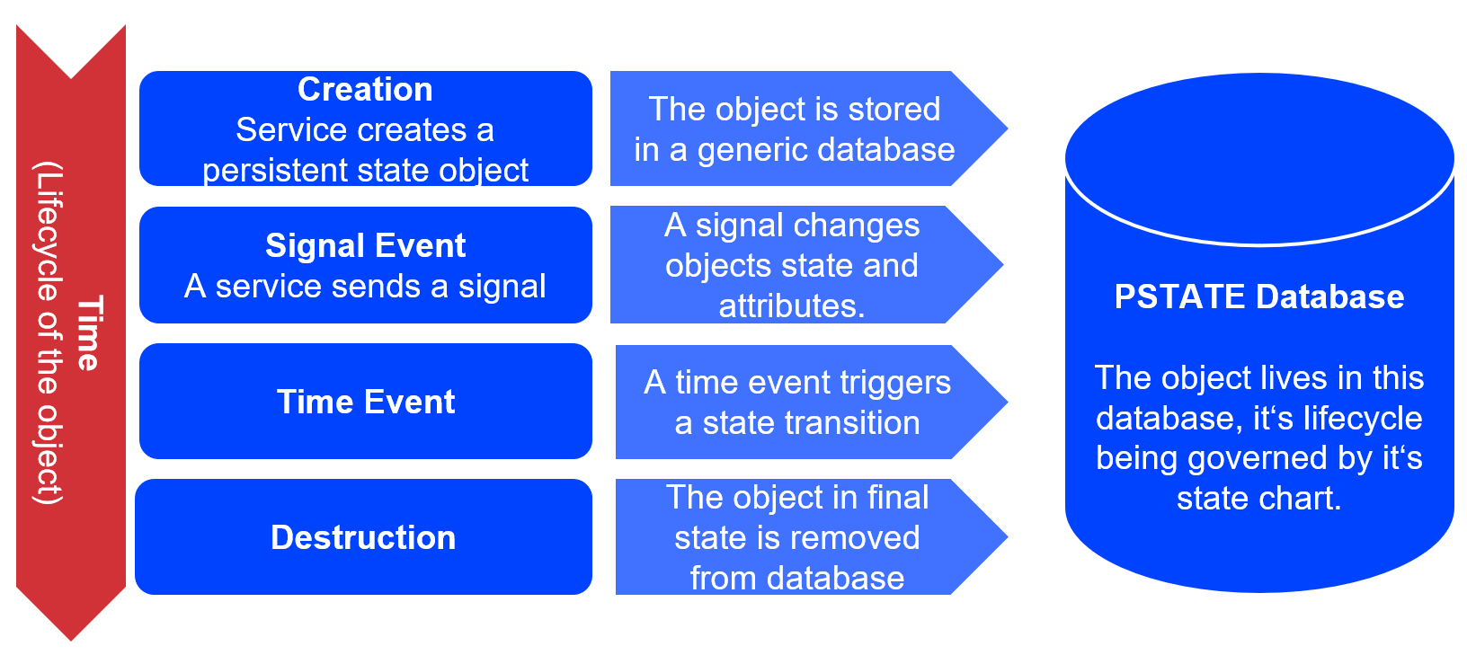
The persistent states (in short: PStates) contain information on the process steps, the content of persisted variables and other information. These persisted variables were previously created in the execution flow in the Designer and could be used throughout the entire process.
For more information about PState management in Scheer PAS refer to Persistent State Data Storage in the Designer Guide and, depending on our setup, to Docker: Persistent States of Containerized xUML Services or Kubernetes: Persistent States of Containerized xUML Services.
Root State Machine
Most business processes involve asynchronous processing and require to hold states persistent while communicating via asynchronous messages. In UML, this behavior is supported by state machines (refer to xUML Service State Machines in the Designer Guide).
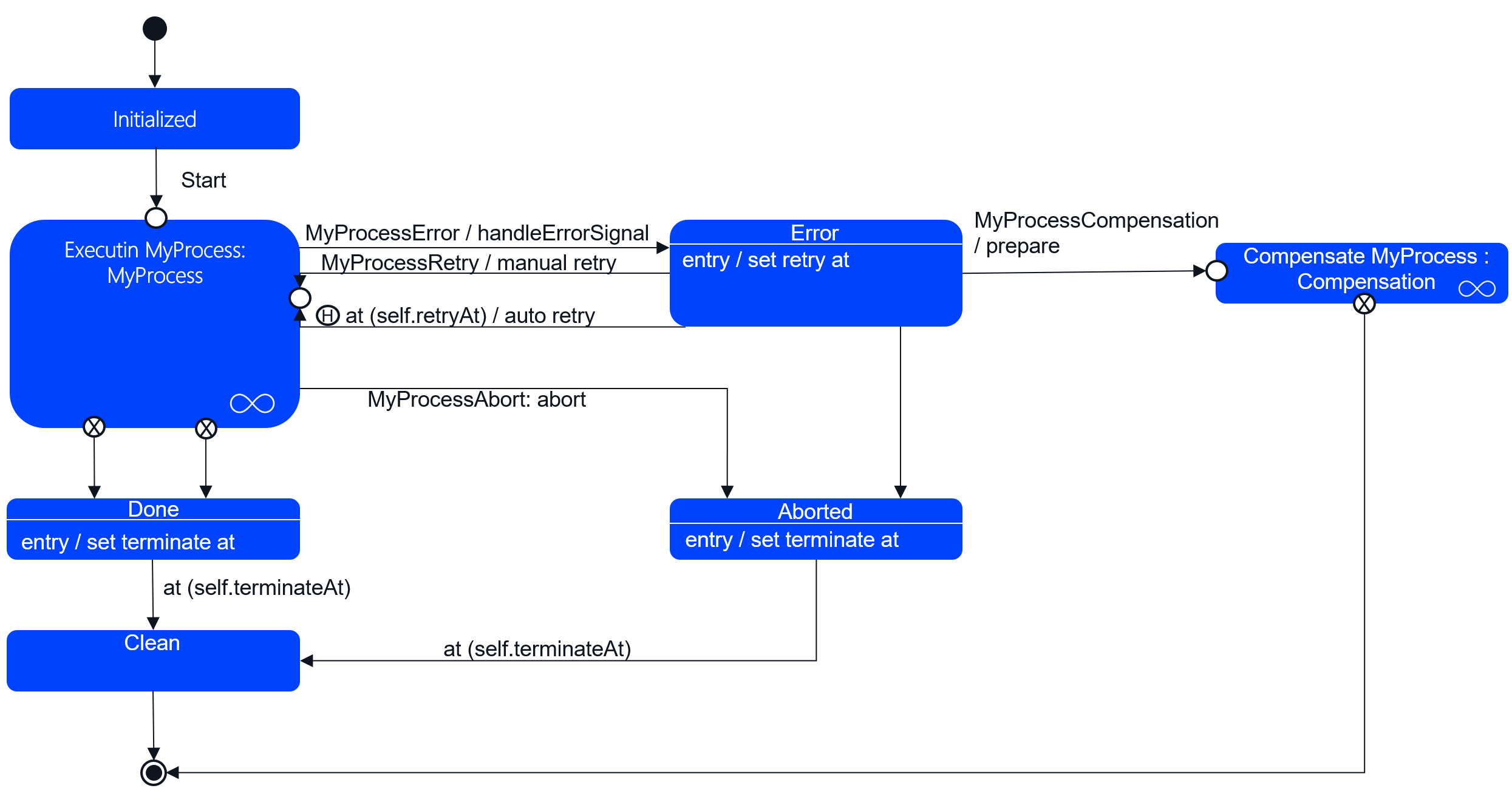
A state diagram defines all the states that a process instance can assume - including the start and end states. While in a state, the process instance can receive asynchronous messages via signals, e.g. an abortion signal. Changes of state are referred to as transitions.
For each BPMN process that has been modeled with the Designer, the compiled xUML service contains one standard root state machine diagram that supports error handling and compensation as well as history states.
For more information about the root state machine and the individual states refer to State Transitions of the Root State Machine in the Designer Guide.
API Management
All service APIs are created during deployment. They can then be tested using a test interface, which is accessible via Designer or through the service details in the PAS Administration. However, the service APIs are initially only available internally within the platform. To make your APIs available externally, for example to your partners, you can use API Management. You can easily import your service APIs from the PAS Administration to API Management.
In API Management, APIs represent real backend APIs (Application Programming Interfaces). An API is also known as a service, meaning anything that can be invoked remotely by some sort of client. API Management provides a way to turn unmanaged (raw) back-end APIs into managed APIs by attaching policies to them. A policy is a rule or a set of rules API Management uses to manage access to your APIs. API Management enables you to secure your APIs, expose them to the outside, control access to the APIs, and analyze their collected metrics. The API Developer Portal grants controlled external access.
Refer to The Concepts of API Management in the API Management Guide for further details.
Administration
The Scheer PAS platform offers a range of management components such as:
-
PAS Administration: After deployment, developers and administrators can manage the services in the PAS Administration. The administration application allows operation and management of deployed xUML services and, with special user permission, PAS platform services, including container statuses, endpoints, logs, service configuration, and persistent state objects. Service administration includes a deployment wizard for direct deployment without the Designer.
Refer to Administrating the Platform Components in the Administration Guide for details. -
User Management: User administration is integrated with identity management but offers a more user-friendly interface and the ability to create and assign new namespaces (profiles).
Permissions (access to other PAS components such as API Management or Log Analyzer), are assigned in the user administration and mirrored in the identity management.
Refer to Managing Users in the Administration Guide for further details. -
Identity Management: The identity management is based on Keycloak. This open-source identity and access management solution enables the implementation of various authorization concepts, such as SSO or integrations with third-party systems. It offers more extensive configuration options than the upstream user management.
Refer to Working With the Identity Management in the Administration Guide for further details.
Analysis
The Scheer PAS platform also supports developers and users in the ongoing analysis and optimization of services. Developers can use the Analyzer for debugging and regression tests, the Log Analyzer assists them with troubleshooting, the xUML Service Monitor with alerting. Users, on the other hand, can use Process Mining to visualize and evaluate processes or process data and KPIs (if configured). Both Log Analyzer and Process Mining are accessible via the PAS Portal (permissions required). The Analzyer is a separate tool that must be installed on the development computer.
-
Log Analyzer: The Log Analyzer uses OpenSearch for data storage and OpenSearch Dashboards for log analysis. OpenSearch Dashboards allow you to search, view, and visualize data in charts, tables, and maps. Standard retention time for logs is 30 days.
Refer to Analyzing Logs for an extensive documentation on this PAS component. -
Process Mining: Process Mining investigates service process flow issues, identifies causes, and evaluates data. The analytics collector service collects transaction log data and stores it in an operational data warehouse. Users can visualize the data in customizable dashboards, requiring proper configuration of the collector service, retention time, and log level.
Refer to our Process Mining Guide for an extensive documentation on this PAS component. -
Analyzer: The Analyzer is a tool to support PAS developers with the tasks of runtime analysis, troubleshooting of distributed systems and regression testing. It allows you to inspect the execution path of a deployed xUML service asynchronously, and you can review this trace graphically in order to debug your service, or verify its correct functionality.
Refer to our Analyzer Guide for an extensive documentation on this PAS component. -
xUML Service Monitor: Allows developers to define events that trigger alerts for specific user groups when errors occur.
Refer to Monitoring xUML Services for an extensive documentation on this PAS component.
Related Content
Related Pages:
Related Documentation: