You need to perform two steps to implement executional parts to your model:
- Provide all necessary data types and operations for the implementation of your process. These types and operations reside in the Service panel of the BPMN editor.
- You can use the Base Types that are provided with the Designer.
- You can create other necessary types yourself in the Implementation section.
Refer to Modeling Data Mapping for further information. - You can import a library that provides additional types and operations.
Refer to Designer Administration > Libraries for further information.
- In the second step, select data types and operations from the Service panel, and add them to your process at the right places.
- How this is done will be explained in this chapter.
Adding Operations
| Select the operation you want to use from the service panel. Drag & drop the operation to the operations flow in the execution pane. You can do this with any operation: Operations from your data model or the Base Types, as well as operations from imported libraries or connectors. |
| When the operation has been added to the operations flow, the displayed pins indicate needed object flows. Hover over a pin to see the name and the type of the expected object flow. |
| Pins on the left of the action node indicate needed incoming object flow. |
| Pins on the right indicate outgoing object flow. |
| To provide the necessary input data to the operation, you need to connect its pins with corresponding variables. |


Pin Highlighting
While dragging the object flow, the color of the pins changes to assist you with finding matching connection points. A pin turns red if an object flow cannot be created at all. You cannot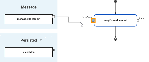
When you start dragging an object flow, all pins of the same type and multiplicity are marked blue.
Blue pins indicate that this pin is a valid target for the object flow.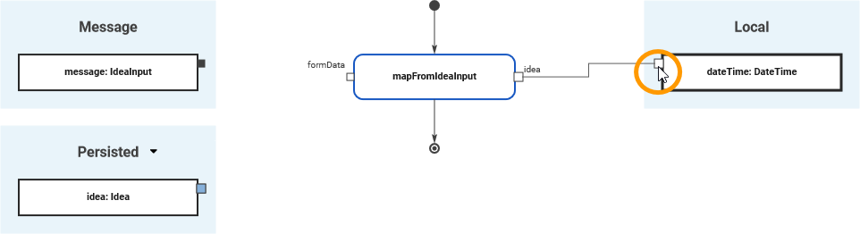
White connection points of variables indicate that you are trying to connect variables that do not have the same type or multiplicity.
The connection point is marked in white when you have reached it with the mouse pointer.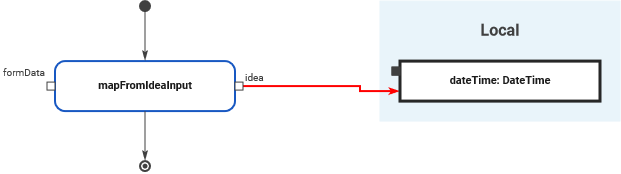
It is possible to draw an object flow to an invalid connection point but the relation will be invalid and displayed in red. 
Static And Non-Static Operations
Operations can be static or non-static.
| Static operations are like functions. They have no self context, and thus no target pin - only input, output, and return pins. |
| Non-static operations are related to a specific type. When added to the execution pane, they provide a target pin in addition to the parameters. Here, the user must provide an object of the related type. |
| To determine the target of a non-static operation, you can:
|


Overview
Content Tools