Executions are modeled in execution diagrams. Refer to Modeling Execution for more information on how to create an execution diagram.
| Select the element you want to start the object flow from. It can be a variable (Message, Persisted or Local) or a parameter pin of an execution step (operation). Click a connection point and start dragging out an object flow. |
| Draw you object flow from one pin to another. An output pin can be connected to more than one variable. Depending on which data is required, you can use variables from the Message, Persisted or Local section. |
 | Object flows on the execution pane are routed automatically. Use the execution pane context menu to change the algorithm of the relation path. |
| You can select an object flow to highlight it in blue. In larger models this helps to track the paths more easily. |
| You can also hover over an object flow to highlight it in black. |


Pin Highlighting
While dragging the object flow, the color of the pins changes to assist you with finding matching connection points. A pin turns red if an object flow cannot be created at all. You cannot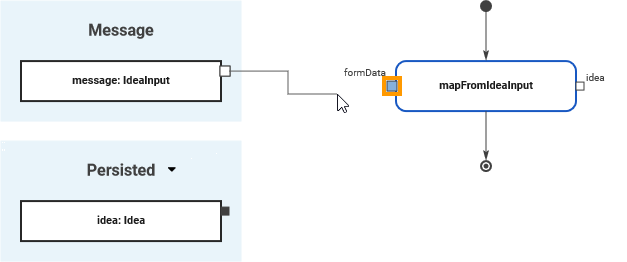
When you start dragging an object flow, all pins of the same type and multiplicity are marked blue.
Blue pins indicate that this pin is a valid target for the object flow.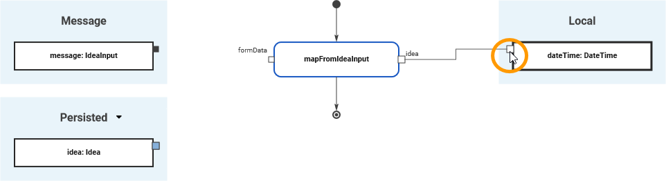
White connection points of variables indicate that you are trying to connect variables that do not have the same type or multiplicity.
The connection point is marked in white when you have reached it with the mouse pointer.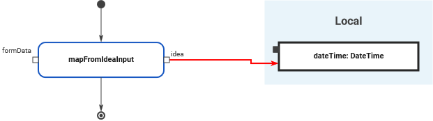
It is possible to draw an object flow to an invalid connection point but the relation will be invalid and displayed in red. 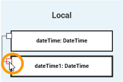
Overview
Content Tools