Designer services are executable UML (xUML) services. This page describes
-
how the definitions of your BPMN executions in the Designer are compiled to UML,
-
how they are presented in the Analyzer, and
-
where the related execution is implemented.
Refer to Browsing Through the Execution Path of a Designer Service for more information on how to find the related implementations within the trace data.
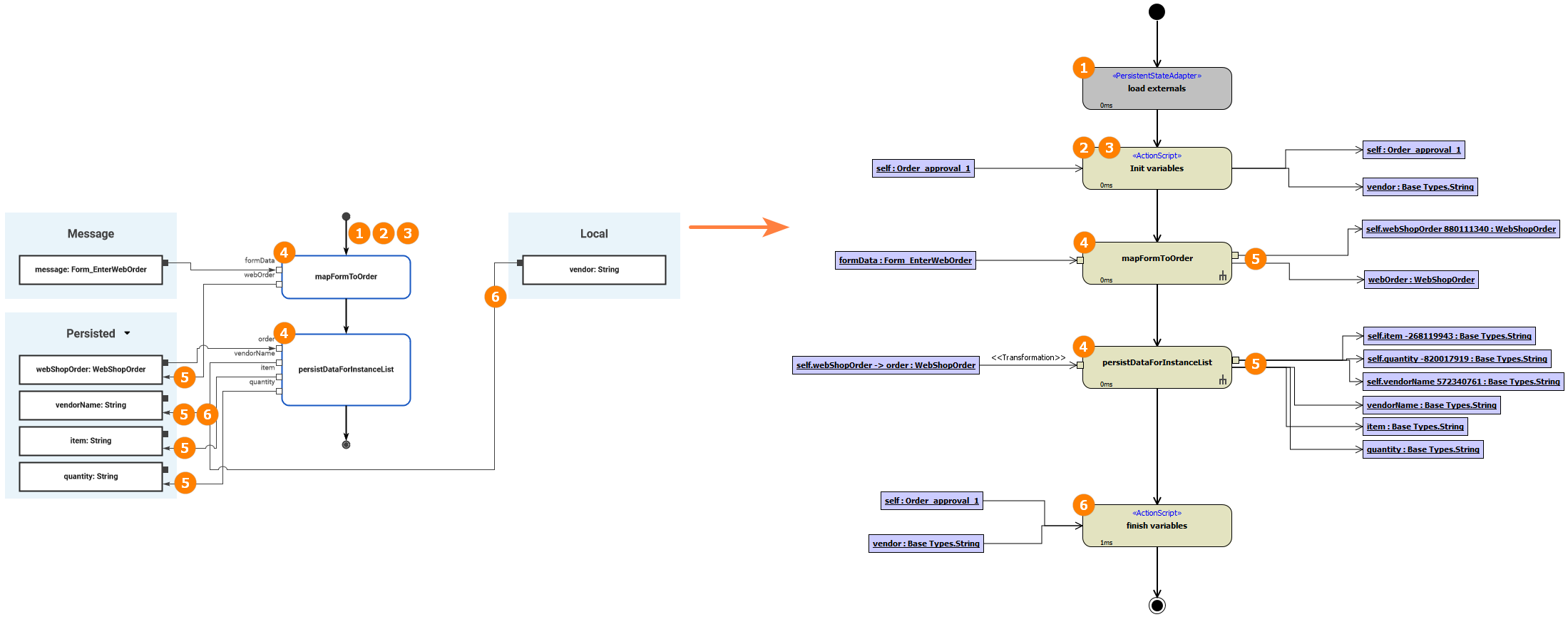
The example below shows the execution diagram of the BPMN user task Enter web order of the Designer tutorial in comparison to the UML behavior behavior_Enter_web_order that has been generated by the Compiler.
The numbers indicate the relation between the two representations, and also the order in which the steps are performed.
|
Ref. |
Action |
Description |
Generated to |
|||
|---|---|---|---|---|---|---|
|
On Exit |
Get Data |
Decision |
On Event |
|||
|
(1) |
load externals |
Load external persisted data Some of the data that you have defined as to be Persisted, are stored to external properties of the state machine. This concerns complex objects and blobs.
|
|
|
|
|
|
(2) |
Init variables |
Assign default values Persisted variables get their default value assigned before the first operation is executed. This means the following:
Persisted Property Defaults Please note that default values for persisted variables are not initialized this way. For these, stereotype <<E2EAttribute>> is applied in the persisted state class, and the the default value is defined via a tagged value on the property itself.
|
|
|
|
|
|
(3)
|
Assign local variables In this step the following is assigned:
The value assignment that happens in this step overwrites any default values assigned in the previous step. |
|
|
|
|
|
|
(4)
|
|
Perform operation calls All execution operations are called one after the other in the order specified in the execution diagram. |
|
|
|
|
|
(5)
|
|
Store data from operation calls Out/Return parameters are stored. Depending on how this is modeled in the Designer, they are either set to a property of the persistent state class (persisted variables, see example above), or to a local variable or the return parameter of the execution. |
|
|
|
|
|
(6) |
finish variables |
Persist local variables The persistent state properties (persisted variables) are updated from:
|
|
|
|
|