Designer services are executable UML (xUML) services. This page describes
-
how the BPMN definitions from the Designer are compiled to UML,
-
how they are presented in the Analyzer, and
-
where the related execution is implemented.
Most examples from the table below are taken from the Designer tutorial service.
Refer to Browsing Through the Execution Path of a Designer Service for more information on how to find the related implementations within the trace data.
Use the Find function of the Analyzer to search for the activities listed in the table below.
|
BPMN Element |
UML Element |
Activity |
Description |
|||
|---|---|---|---|---|---|---|
|
|
Process |
State Machine |
|
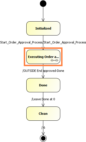
BPMN processes are generated to state machines as described on xUML Service State Machines. A standard root state machine contains the implementation of the BPMN process as a sub state machine. The Analyzer shows the trace of the root state machine in the Main tab. The actual BPMN implementation is in a sub state machine Executing <name of the process>. |
|
|
|
|
Start Event
|
On Event |
Transition |
behavior_<name_of_
|
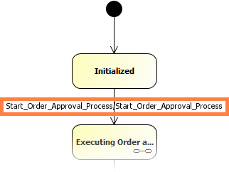
The root state machine of the xUML service has a state Initialized. All kinds of start events are generated as transitions from this initial state to an entry point to the sub state machine. Apart from the start events, all other BPMN elements are implemented to the sub state machine mentioned above (Process). |
|
|
|
End Event |
On Event |
Transition |
behavior_<name_of_
|
The end event is called in an action script on the transition to the final state of the sub state machine. The activity is called behavior_<name_of_the_end_event>. |
#
|
|
|
Border/Intermediate Events |
On Event |
Transition |
behavior_<name_of_
|
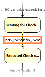
All kinds of border and intermediate events are generated as transitions from the source to the target state. |
|
|
|
Service Task |
On Exit |
State entry |
behavior_<name_of_
|
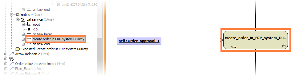
After a service task has been executed, the state machine is in a state Executed <name of the service task>. The On Exit execution of service tasks is generated to the entry activity of this very state |
|
|
|
User Task |
Get Data |
|
get_<name_of
|
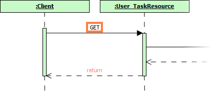
The GET request on the user form is performed on a separate resource of the service called <name of the service>REST.InstanceResource.<name_of_the_user_task>Resource. You can find it below the node BPMN_RESTService. |
|
|
On Exit |
Transition |
behavior_<name_of_
|
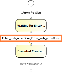
The On Exit execution of user tasks is generated to an activity called behavior_<name of the user task>. The implementing activity is called on the transition to the next state of the sub state machine. The screenshot on the right shows the generated UML for the user task called Enter web order . |
|
||
|
|
Receive Task |
On Exit |
Transition |
behavior_<name_of_
|
The On Exit execution of receive tasks is generated to an activity called behavior_<name of the receive task>. The implementing activity is called on the transition to the next state of the sub state machine, see also User Task, On Exit. |
|
|
|
Exclusive Gateway |
Decision |
Transition |
choice_<name_of_
|
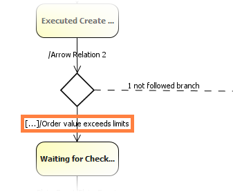
Gateways are implemented as choices, a pseudo state of the sub state machine. The actual check is generated to the transition from the choice state to the next state. The name of the behavior activity is <name of the sequence flow>. Not followed branches and their implementation are depicted as a dead end flow. You can nevertheless check their implementation. |
|