You have learned to open an existing Builder project previously. To start with lesson 1, you will create a new Builder project.
Creating a new Builder Project
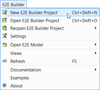
| Click E2E Builder > New E2E Builder Project. |
| Alternatively, you can choose File > Model Execution & Integration > New E2E Builder Project. |
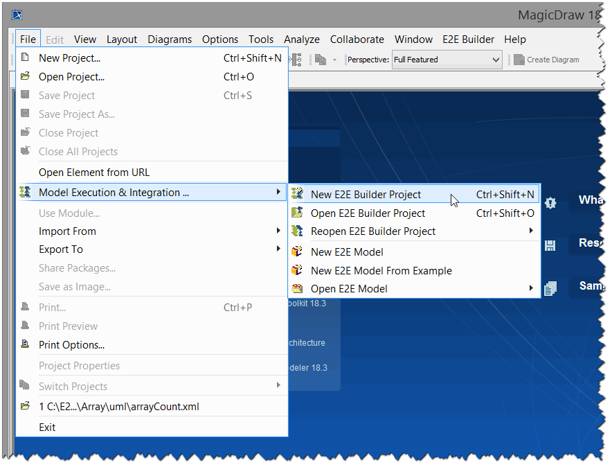
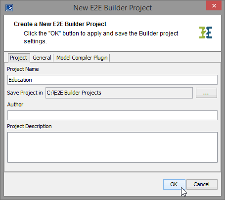
The New E2E Builder Project dialog will open asking you to configure the Builder project settings.
| Set the Project Name to Education. Continue with setting the Builder project path. Click the ... button to open the E2E Builder Directory Chooser dialog. Click the Create New Folder icon You can optionally enter an author name and a project description. |
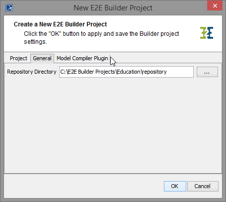
Now, switch to the General tab.
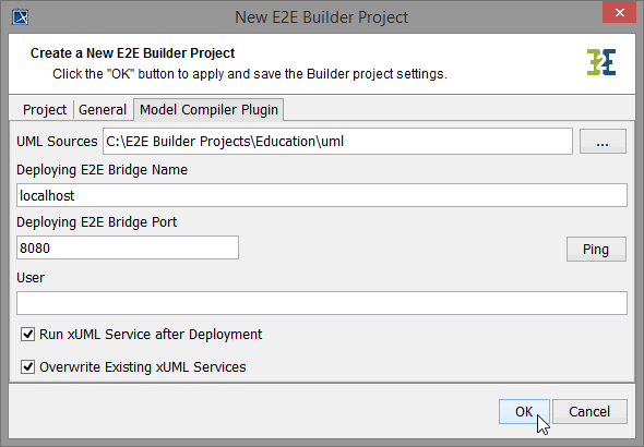
| The Repository Directory is set by default. All repositories of compiled XMI files of the current Builder project will be stored in this path. The repository path will be discussed later again as of testing the service. Do not change the default path that contains the Builder project path. Switch to the tab Model Compiler Plugin. |
| All UML models (XMI files) you create in this Builder project will be stored in the UML Sources path. If you have purchased a dedicated E2E Runtime, compiled xUML services are deployed by the Bridge defined on this dialog. In this example this is the Bridge on localhost that is listening on port 8080. Click OK. |
For detailed information about these settings, refer to the E2E Builder User's Guide.
The settings are applied to the Builder project Education. All XMI files of a Builder project are in reference to the Builder project settings. You may change the project settings at any time by choosing the menu items E2E Builder > Settings. All actions that are executed afterwards will be based on the new project settings.
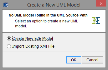
| The next screen will offer you to create a new model or to import an existing model. Select the option Create New E2E Model and click OK. |
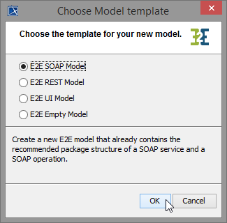 | The Builder offers four standard templates for a new model. As you will create a Web service during the three lessons, choose E2E SOAP Model. Click OK. |

The E2E model template contains several pre-defined UML elements that are necessary to create integration services with the Bridge. It also provides a default package structure for your services and a frontend SOAP interface as a starting point.
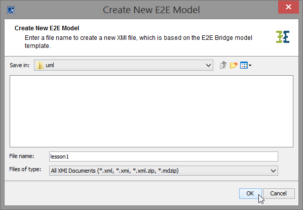
| Until now, the XMI file is not yet saved in the Builder project. You have to enter a file name first. The file name BuilderUML.xml is suggested. |
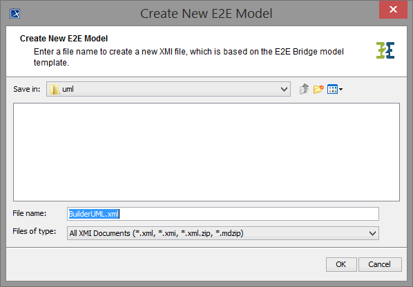
| Replace the file name BuilderUML with lesson1. Click OK. |
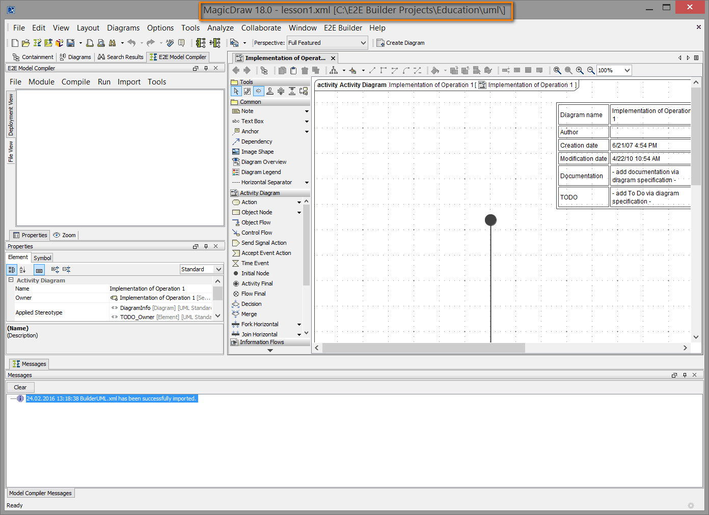
The XMI file lesson1.xml containing the UML model has been saved in the Builder project Education and is already opened in MagicDraw. The activity diagram Implementation of Operation 1 is displayed as shown in the picture below.
Note that in the MagicDraw title bar the name of the currently opened UML model file lesson1.xml is displayed. It is followed by the full path of the Builder project in brackets: [C:\E2E Builder Projects\Education\uml\].
E2E Builder Tools
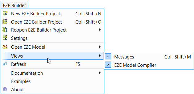
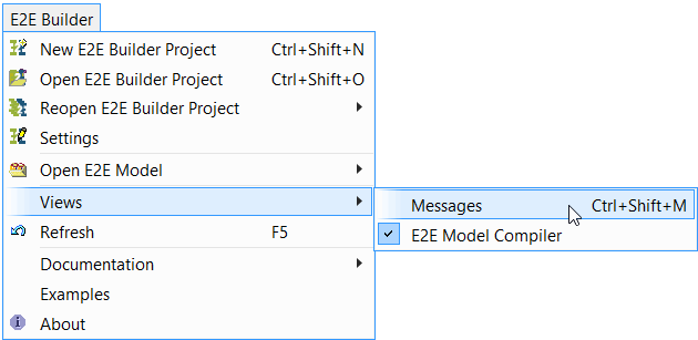
Select E2E Builder > Views. This menu provides menu items to open and close the Messages window and the E2E Model Compiler.
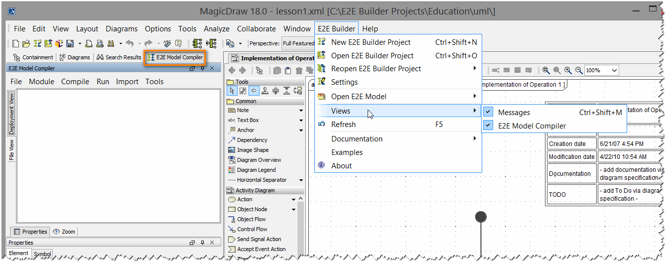
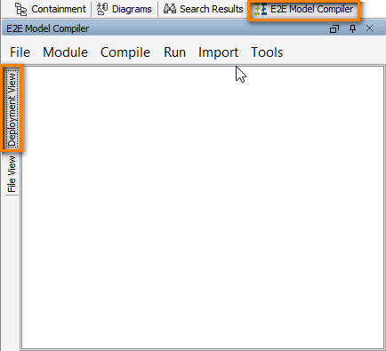
 | The Messages window and the E2E Model Compiler menu item are currently active (the Model Compiler is displayed on the left side, see picture above). In general, the Model Compiler should not be closed. However, if it was closed for some reason, you can open it again with this menu item. |
| The Model Compiler window (with the tab Deployment View selected) is still empty, because you have not defined any deployments yet. Its functionality will be explained later on in the context of service components. |
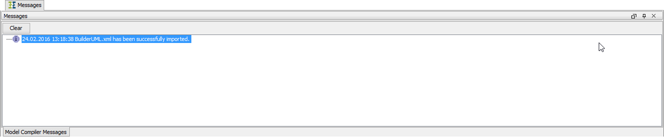
On the lower left side, the E2E Messages Window is displayed. Whenever the Builder writes messages to it, it will be opened automatically. It displays status messages, the result of compilation, and other important messages.
You can close the window at any time by clicking X in the upper right corner in order to gain more room for the diagram pane.
| In order to re-open the E2E Messages Window, select E2E Builder > Views > Messages from the main menu or press Ctrl - Shift - M. |
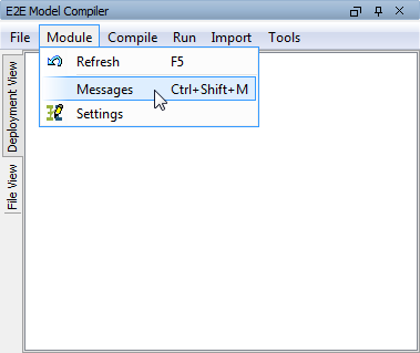
| Another way to open the Messages Window is selecting Module > Messages from the Model Compiler menu. |
Now, close the E2E Messages Window.
Navigating in UML Diagrams
On the upper left side, you can see the structure of the UML model you just saved. This structure is called containment tree and will be discussed step by step during the lessons.
| On the lower left side, you can use the Zoom tab to navigate in UML diagrams. This is, for instance, helpful for class diagrams having a lot of classes. Click the area surrounded by the blue frame and keep the mouse buttons pressed while moving it to the desired position in the activity diagram (drag and drop). |
| By clicking the blue frame you can resize and zoom into and out of the activity diagram on the right side (diagram pane). |
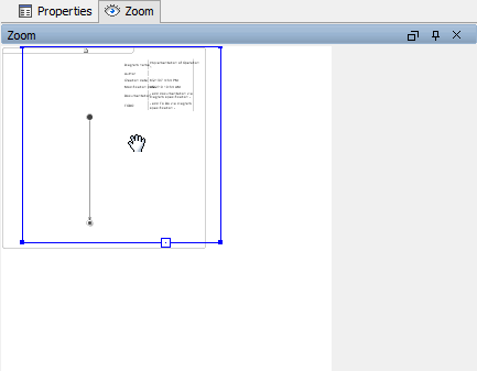
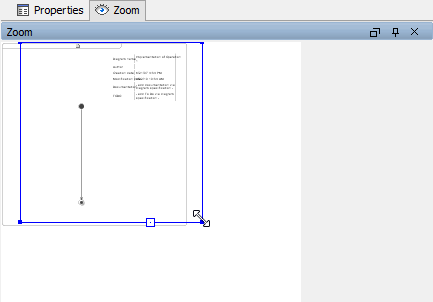
Diagram Info
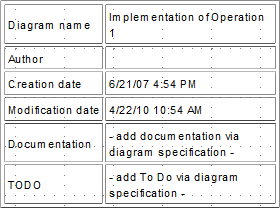
In UML diagrams, you can display a diagram info box in the upper right corner containing the diagram name, the author who created the diagram, creation and modification date, a short documentation, and a todo field. The todo content is searchable in MagicDraw.
In order to switch on or off the diagram info, click the right mouse button in the diagram to open the context menu. Then, select Show Diagram Info.
MagicDraw Projects Versus E2E Builder Projects
In MagicDraw, all UML models respectively XMI files are called project. You can open them without having E2E Builder installed via the File > Open Project menu.
Working with the Bridge, all UML models, which belong to your software project, are organized within a Builder project, which has its own settings. To work with Bridge models, you need to open a Builder project first in order to edit, compile, and deploy the contained UML models. All models are located in the uml folder of the Builder project.
In the title bar of the MagicDraw window, the name of the currently opened model (lesson1.xml) is shown, followed by the path of the currently opened Builder project displayed in brackets [C:\E2E Builder Projects\Education\uml\].
In the Switch Projects toolbar, you can see all UML models (XMI files) currently opened in MagicDraw.
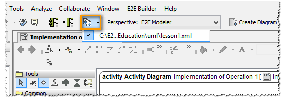
If this toolbar is not displayed yet, enable it via View > Main Toolbars > Switch Projects. Alternatively, you can right-click into the toolbar area and select Switch Projects from the context menu.

On this Page:
Overview
Content Tools