
You will now start to draw a use case according the previously described assignment.
In MagicDraw on the left, you find the containment tree, which has a pre-defined structure containing UML elements. The folders in the containment tree are called packages.
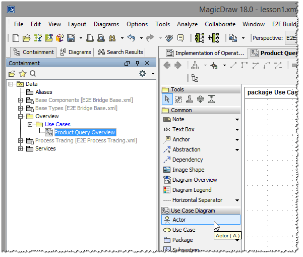
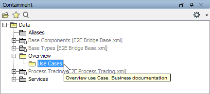 | Expand the package Data / Overview in the containment tree by clicking on the plus sign, and select the package Use Cases. You will now start drawing an overview use case diagram describing the Web service. |
Creating the Use Case Diagram "Product Query Overview"
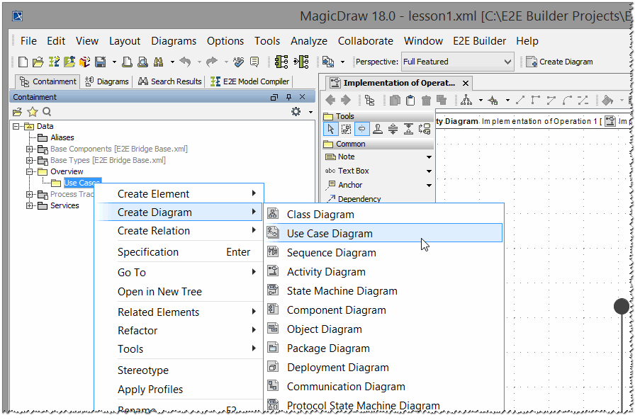
Open the context menu by clicking the package Use Cases with the right mouse button. Select Create Diagram > Use Case Diagram as shown in the picture below.
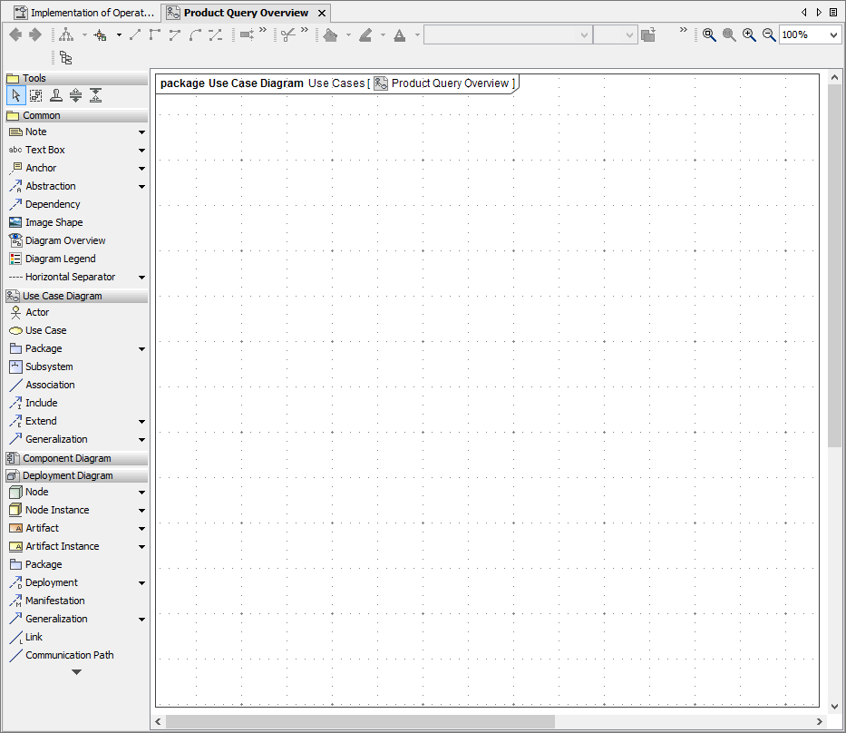
A new use case diagram will be opened with the default name Untitled1 shown in the containment tree on the left. The diagram name is in editing mode, so you can just enter the new name Product Query Overview and press the Enter key.
The empty use case diagram created by you is shown on the diagram pane. If you want the diagram info to be shown, select Show Diagram Info from the diagram's context menu. For more details refer to section Using E2E Builder .
You will now draw the UML elements of the main use case diagram.
As discussed before, the use case view models the functionality of the system as perceived by outside users, which are called actors. You will start to define the project scope of the product query in the main use case diagram, which will contain one use case at the beginning. The use case will represent the "business" goal of this first lesson according the previously described assignment.
| Select the Actor symbol from the diagram toolbar with the left mouse button. |
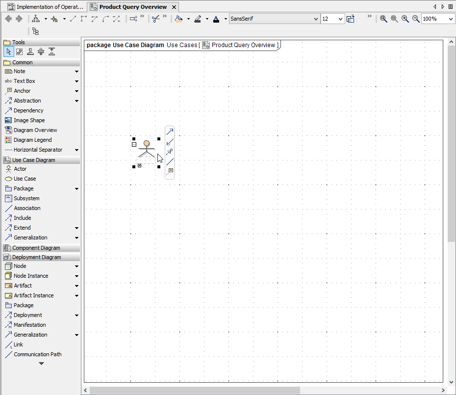
| Move the mouse over the use case diagram and click again. The actor will be placed on the diagram pane as shown in the picture below. |
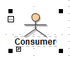
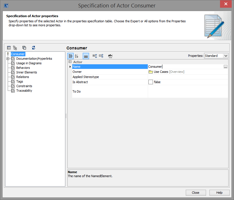 | Double-click the actor symbol. In the upcoming dialog, enter Consumer in the Name field and click Close. |
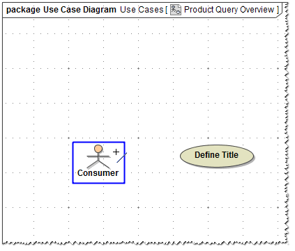
| The actor's name Consumer is now displayed with the actor symbol. |
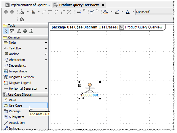 | Consumer is the first element of the use case diagram and is also displayed in the containment tree on the left. In the next step, define the first use case, which describes the functionality of the Web service you will create in the first education lesson. Select the Use Case symbol from the diagram toolbar. |
Move the mouse over the use case diagram and click again. A use case symbol will be placed on the diagram pane.
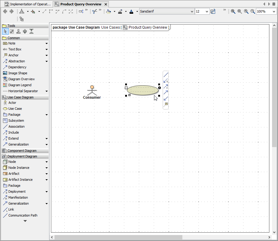
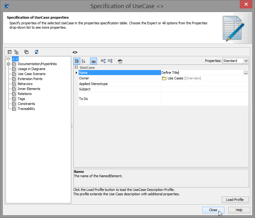
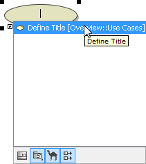
Double-click the symbol and name it Define Title. Click Close.
| |
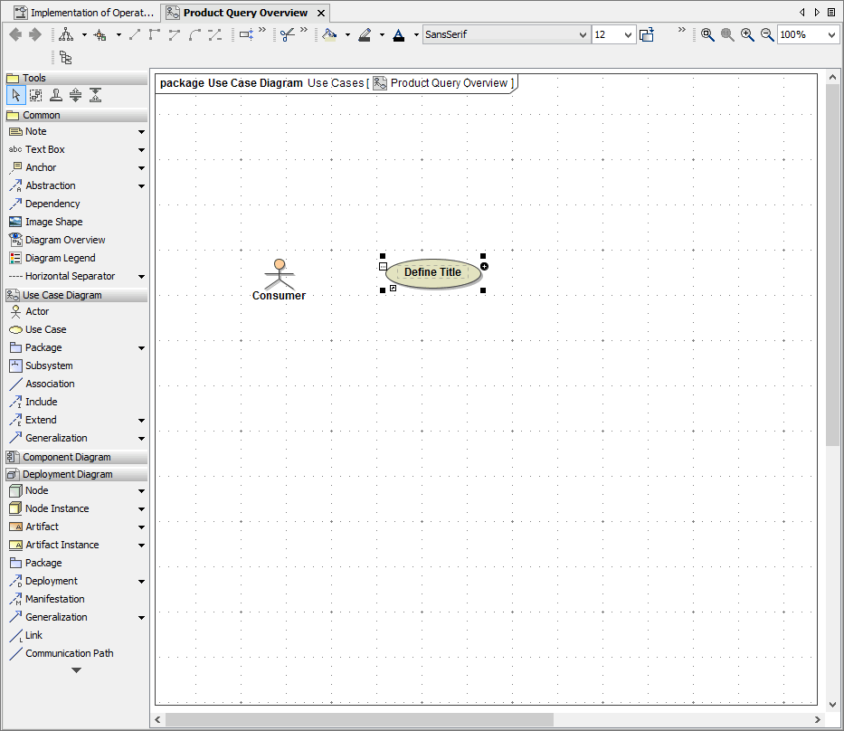
The use case diagram now contains two elements: the actor Consumer and the use case Define Title.
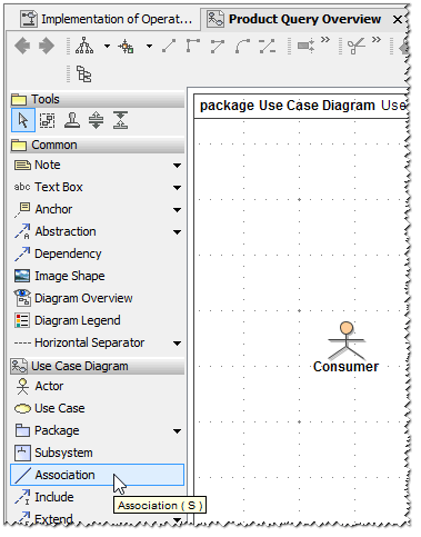
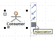
| In the next step, you will define the association between the actor and the use case. Associations indicate that an actor is involved in the interaction of a use case. Select the Association symbol from the diagram toolbar. |
| Move the mouse cursor over the actor, which will be surrounded by a blue activation frame. Then, click the actor symbol and … |
| … move the cursor over the use case. When the use case is surrounded by a blue frame, click again. The association between the actor Consumer and the use case Define Title will be drawn in the use case diagram. |
| Alternatively, you can also click the actor Consumer and choose the symbol Association from the Smart Manipulator Toolbar. Directly move the mouse cursor over the use case and draw the association. |

The overview use case diagram describing the first step of the Web service is finished.
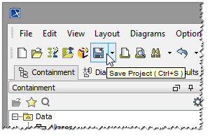
| Save Note that the color of the new elements in the containment tree change from blue to black. |

Creating the Use Case Diagram "Define a Title"
The next task is to model the functionality of the Web service that meets the objectives of the first education lesson. The required interaction will be documented in another use case diagram called Define a Title.
| Select the package Data / Overview / Use Cases as shown in the picture on the left. |
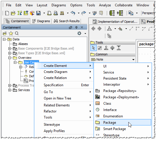
| Click the package Use Cases with the right mouse button, and select Create Element > Package from the context menu. |
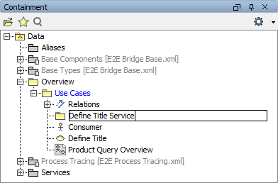
| Enter the name Define Title Service. |
| Click the package Define Title Service with the right mouse button, and select Create Diagram > Use Case Diagram from the context menu. |
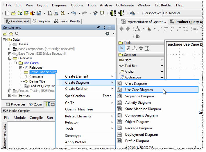
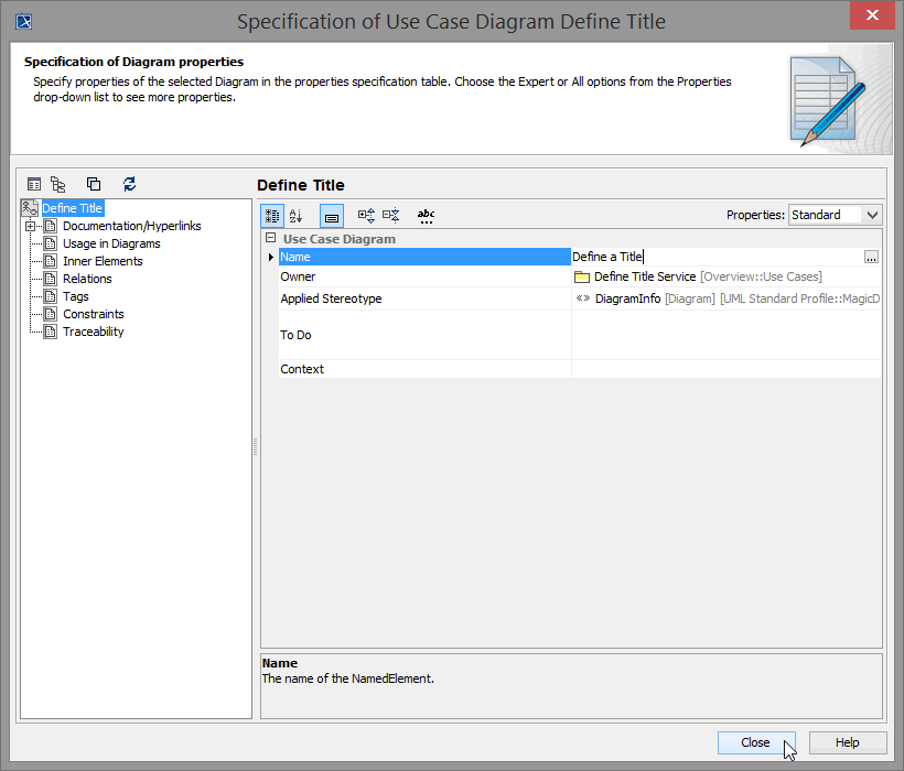
A new use case diagram will be opened with the default name Untitled1. Change the name to Define a Title.
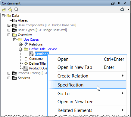
| Alternatively, it is possible to change the name by opening the use case diagram specification dialog via its context menu Specification. |
| Enter the new name in the Name field. |
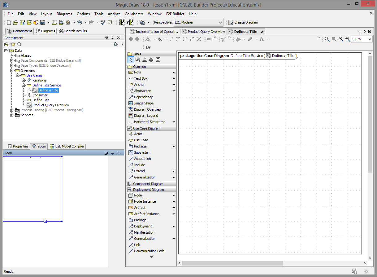
You have just created a new use case diagram. It is shown in the containment tree on the left.
In the next step, you will draw the use case of your first Web service. As discussed in the beginning of this lesson, the Web service will take a string as input, and convert it to upper case. The Consumer defined as an actor in Product Query Overview will be also the service consumer - so you will use the same actor.
| Select the actor Consumer from package Define Title Service. |
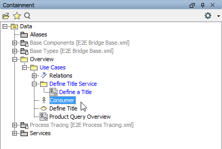
You will reuse the actor, because it is always the same one that will take part in all following actions. Select Consumer with the left mouse button, keep the button pressed, drag it to the diagram pane, and drop it.
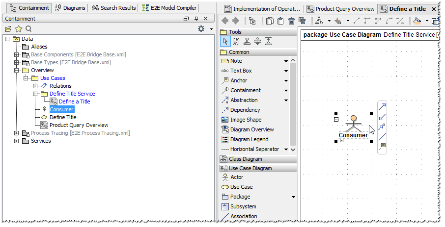
As you reuse the actor from the package Data / Overview / Use Cases, it will not be copied to the package Data / Overview / Use Cases / Define Title Service in the containment tree.
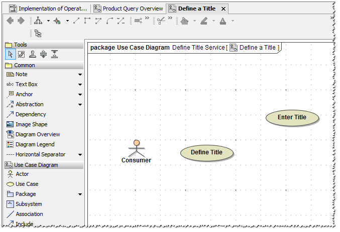
Next, you will draw a use case. Select the use case icon from the diagram toolbar and drop it onto the diagram pane. Right after doing this, the use case is in the editing mode. Start entering the name Define Title and confirm the entry by pressing Enter or by clicking outside this use case.
This is the most efficient way to name a use case. If the use case does not accept your typing, try to re-select the UML element.
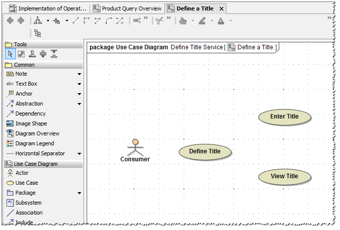
Draw a third use case and name it View Title.
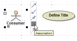
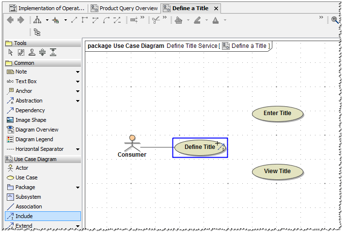
| Now, you will define an association between the actor Consumer and the use case Define Title. Use the smart manipulator toolbar that appears when you select the actor symbol. Click the association symbol and drop it onto the use case Define Title. |
Enter Title and View Title are two use cases that are part of the use case Define Title. Therefore, you will connect them using an Include relation.
| You have the choice of either using the Include symbol in the diagram toolbar or in the smart manipulation toolbar. |
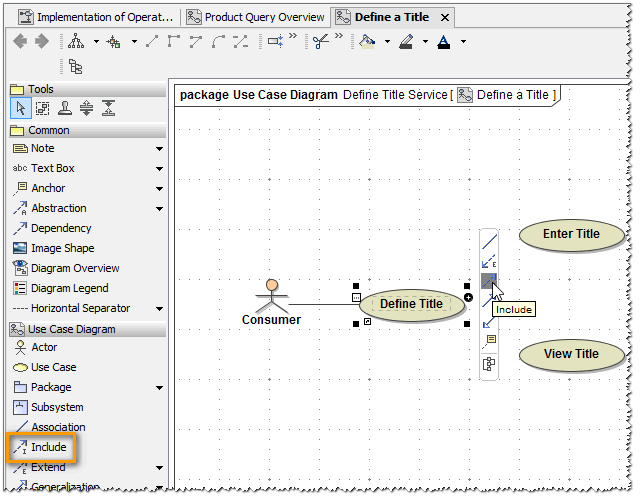
MagicDraw prevents making wrong connections e.g. using an include relation to make a connection from an actor to a use case. If a connection is not possible, the object's activation frame is displayed red. 
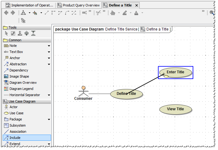
Now, select the include relation from the diagram toolbar and move the mouse over the use case Define Title. When the blue frame appears, click it.
Move the mouse over the use case Enter Title. When the blue frame appears, click again. Note, that the relation will be labeled with the stereotype <<include>>.
Draw another include relation between the use cases Define Title and View Title.
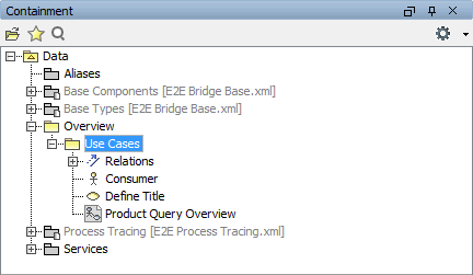
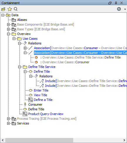
The use case diagram is now containing three use cases Define Title, Enter Title, and View Title that are also visible in the containment tree. The actor Consumer was reused from the use case diagram Product Query Overview.
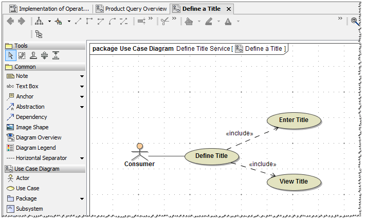
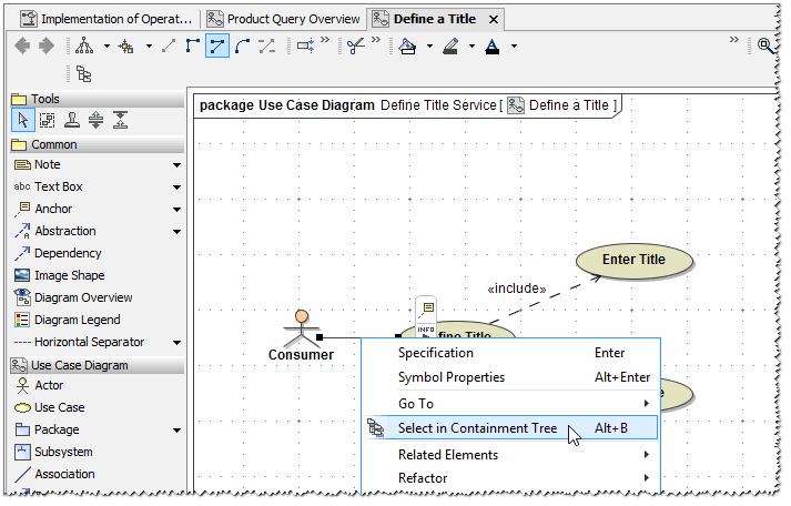
All relations (one association and two includes) can be found in the containment tree. MagicDraw allows you to jump from a UML element of the diagram pane to its location in the containment tree.
Right-click the association between actor Consumer and use case Define Title and select Select in Containment Tree from the context menu.
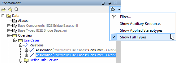
The association is highlighted in the containment tree. If you expand this node, two association ends will be displayed. They have no names, but their types are displayed behind the colon (Define Title and Consumer).
You can display the fully qualified types by choosing the option Show Full Types at the top of the containment tree.
| Open the Association specification dialog by double-clicking the Association node in the containment tree. |
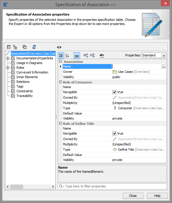 | You will notice that the elements Define Title and Consumer are assigned to association end Role of Define a Title and Role of Consumer. You optionally may enter names for each end of association. This would provide more advanced search possibilities in complex use case diagrams. |
Close the window and save ![]() the UML model.
the UML model.

On this Page:
Overview
Content Tools