Follow Our Example User Story
David has now designed the business process model and the necessary user interfaces (forms). But his goal is to develop an executable application. So now he needs to bring his process to life and add the executional parts to his process. In the first step of the process, order data is entered into a web form. But the entered data should also be available during the process, therefore David has to define the execution of the data.
You are going to help him with that task.
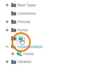
The execution part of a process is created in an execution diagram. To open the execution diagram of a BPMN element, just click on it.
| Click on user task Enter web order in the BPMN diagram. The related execution part will be displayed on the execution pane below the BPMN diagram. Since no execution has been implemented yet, the panel shows an empty UML diagram with only an incoming message variable. This message will contain the form data. |
| In the previous tutorial step you have already assigned Form_EnterWebOrder to user task Enter web order. Therefore the message variable of Enter web order already is of type Form_EnterWebOrder meaning that the input data of form Form_EnterWebOrder now will be sent to the process with this message. |

Persist the Form Data
You need to persist the incoming order data that comes with this message to be able to access the order data throughout the process. Library ERPOrderInterface provides a data type WebShopOrder for this.
Create a Variable to Hold the Data
| Expand library ERPOrderInterface in the Libraries folder and select classs WebShopOrder from the list of available types. |
| Drag and drop it to the Persisted area to create a persisted variable. |
| A persisted variable is created. As a name, it gets assigned the name of the type. You can change the name of persisted variables to one of your own choice by double-clicking the name. Find more information on persisted variables on Persisting Data in the Designer guide. |


Create a Mapping Operation
To actually persist the incoming data from the form into variable webShopOrder , you need to map the information between the two. This can easily be done with a mapping diagram. Mapping diagrams reside in the Implementation folder in the service panel and are implemented to class operations.
| Add a new package Mapping to Implementation. |
| Add a new class Shop to Implementation > Mapping. |
| Add a new mapping operation mapFormToOrder to Implementation > Mapping > Shop. |
| In the attributes panel of the operation, check that the operation is static. Static operations are independent from the class they reside in. They get and provide data via parameters only. |


The data that should be mapped is provided via operation parameters.
| Add a new input parameter formData to operation mapFormToOrder. |
| Select parameter formData and switch to the attributes panel. As per default, new parameters are of type String. Click icon |
| In the pop-up, search for type Form_EnterWebOrder. Select it and click Save. |
| Add an output parameter webOrder to operation mapFormToOrder. In the attributes panel, change the type to WebShopOrder. |


Create the Mapping Diagram
Now you are ready to create the implementation of the mapping operation. As you created the mapping operation mapFormToOrder, the corresponding mapping diagram is already open in a new tab and shows the data structures to be mapped. On the Input side, you can see the form data, on the Output side, you can see the order object you want to persist the data to. In both sections click on the arrow icon (![]() ) to see the content of each object.
) to see the content of each object.
![]()
| To map the item data, click the This adds an array element to the items array (item [0] in the picture below). Expand it clicking the arrow icon ( |
| Expand the array item [0] to see its content. |
| Now connect the corresponding data items of Input to the Output side with an object flow. While dragging the object flow, the Designer highlights all available targets in blue
|


Refer to Modeling Data Mapping for more information on how to work with the Mapping Editor, and to Mapping Data Structures for reference information regarding data mapping with the Designer.
Add the Mapping Operation to the Process
Finally, you need to add the mapping operation you've created to your process in user task Enter Web Order.
| Click user task Enter Web Order from your process to display the related UML diagram on the execution pane. |
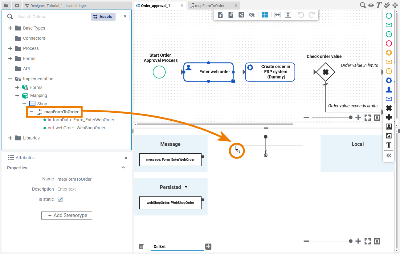
| Select the operation mapFormToOrder you have created in the previous steps. Drag and drop the mapping operation to the activity flow on the execution pane. |
| The operation has been added to the action flow of the execution UML. Pins on the left of the action node indicate needed incoming object flow, pins on the right indicate outgoing object flow. Operation mapFormToOrder needs an incoming object and provides one outgoing object. |


You need to provide the form data you want to map as input.
| Connect the message variable with pin formData of the mapping operation. |
| Connect the output pin webOrder of the mapping operation to the persisted variable WebShopOrder. |
| The form data now is persisted and therefore available throughout the process. For more information on the execution editor in general, refer to Working with the Execution Editor. |


Overview
Content Tools