When you open the implementation of an operation that has been implemented as activity, the activity diagram opens in the activity editor.
| The activity editor consists of different areas: |

Customizing the Activity Editor
| You have several options to adjust the activity diagram editor. When you open the editor for the first time, the default view is displayed:
Refer to Customizing Editors and Panels for detailed information about panel management in general. |
The diagram pane shows the torso of an activity diagram: only initial node and final node are present. This leads to the validation panel showing errors because a control flow is missing.
Refer to the other pages in this chapter for more information on how to draw a valid activity diagram:
- Adding Operations in the Activity Editor
- Drawing the Control Flow
- Adding Local Variables
- Adding Literals
- Adding Comments
- Drawing Object Flow (Activity)
- Adding Parameters in the Activity Editor
- Moving Pins
Modeling in the Activity Editor
While modeling, some general functionalities help you to browse through your model, and to adjust your working location within the model. Refer to Customizing Editors and Panels for more details.
Toolbars
The activity diagram editor features a diagram toolbar in the center top of the diagram pane, and an elements toolbar on the right.
Diagram Toolbar
The activity diagram toolbar assist you during modeling an activity diagram:
![]()
The available tools are:
| Tool Icon | Tool Name | Description |
|---|---|---|
| Select in service panel | Select the related operation in the service panel. | |
| Reload diagram | Click on this icon to reload the activity diagram. |
| Toggle Grid | Use this option to enable or disable the grid on the diagram pane. The grid supports you during modeling: If the grid is enabled, elements snap to the grid points. | |
| Insert/Remove horizontal space | Use this option if you need more or less space on the diagram pane. Click on the pane to display the start line, the second click marks the end line and defines the size of the area to be added. To add space, click from left to right to define the area. If you want to delete a horizontal space, click from right to left to define the area | |
| Insert/Remove vertical space | Use this option if you need more or less space on the diagram pane. Click on the pane to display the start line, the second click marks the end line and defines the size of the area to be added. To add space, click from top to bottom to define the area. If you want to delete a vertical space, click from bottom to top to define the area. | |
| Undo | Undo the previous action you performed in...
If you click Undo in one of the Designer editors, this may also have an effect on the Implementation folder in the Service panel if you performed your previous action there. | |
| Redo | Redo your previous action (after undo). |
Elements Toolbar
The elements toolbar contains all elements that you can create on your activity diagram.
| Icon | Description |
|---|---|
| Add a final node. An activity diagram can have multiple final nodes. | |
| Add an object node. This can be used to store data locally. | |
| Add a decision. Decisions are used to split the control flow based on conditions/guards. | |
| Throw the exception defined by the parameters. If this error is not caught, it will be sent back to the client. For more information, refer to User Defined Errors in the xUML Services Reference Guide. | |
| Add a literal. It can be connected to output parameters, return parameters or pins (action call or throw exception) that do not have incoming relations. |
| Add a comment. This has no effect on the execution, it is just for documenting purposes. |
| Add a mapping operation. |
| Add an action script operation. |
| Add a JavaScript operation. |
| Add an activity operation. |
If you have added an operation via the elements toolbar, it...
- ... resides in the same class as the activity diagram.
- ... inherits the static attribute of the activity diagram by default, i.e. if the activity diagram is static, the new operation is also static.
Activity Diagram Context Menus
You are supported during modeling on the activity diagram pane by various context menus:
Tools Context Menu | |||||||||||||||||||||
|---|---|---|---|---|---|---|---|---|---|---|---|---|---|---|---|---|---|---|---|---|---|
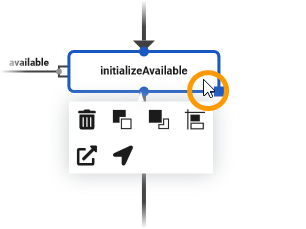
| If you right click on an element, the tools context menu opens. Use it to edit the current element. The following options are available (the options depend on the selected element):
| ||||||||||||||||||||
Extended Tools Context Menu | |||||||||||||||||||||
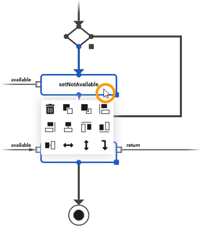
| If you have selected more than one element on the pane, the tools context menu is enhanced with additional options. The available options depend on your selection on the diagram pane:
If you want to align a relation between two elements, mark the pin(s) to apply the corresponding alignment functionality. | ||||||||||||||||||||
Control Flow Context Menu | |||||||||||||||||||||
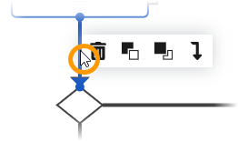
| Right-click a control flow to open the context menu. The following options are applicable to control flows:
| ||||||||||||||||||||
Diagram Context Menu | |||||||||||||||||||||
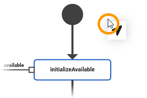
| With a right-click on the diagram pane itself, you open the diagram context menu:
| ||||||||||||||||||||


Keyboard Shortcuts
Find below a list of all keyboard shortcuts that are available in the activity diagram editor.
On this Page:
Related Pages:
Overview
Content Tools