You can step in at the following points of a state and add your own code:
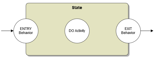
Entry Behavior
Whenever a certain state is entered, an entry behavior is triggered. In the state machine diagram above, activity Check Out Handler is executed, whenever a PurchaseOrder object enters the state Checked out, waiting for closing.
In the assigned activity diagram of the entry handler, the attributes of the persistent state object can be modified using the self keyword. Changes to the object will be persisted automatically.
The state entry behavior is executed, whenever the state is entered, regardless through which transition. Suppose two signals, A and B, may trigger two separate state transitions with the same target. Whenever the target state is entered, the state entry behavior is executed, no matter if signal A or B triggered the state transition.
Figure: State Entry Handler in State Specification
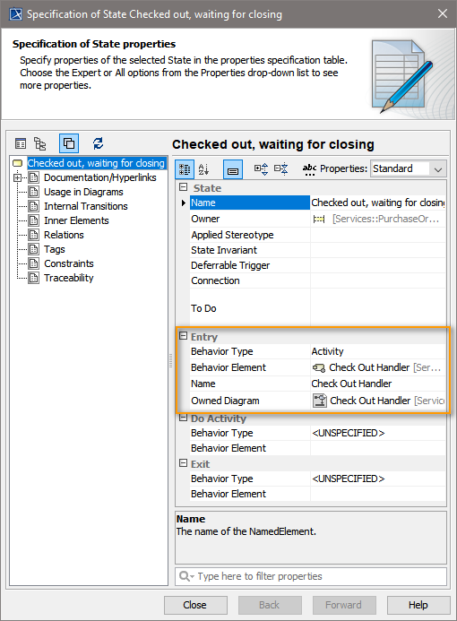
The entry behavior is defined in the Entry compartment of the state's specification dialog
- Behavior Type needs to be set to Activity.
- Then, select or create the implementing activity in the Behavior Element field.
The entry behavior is executed in the same transactional context as the transition. This means that if an error occurs during an entry activity, the rollback will include entry behavior of the target state and the transition.
Exit Behavior
Exit behaviors are very similar to entry behaviors. An exit action is executed whenever a state is left through a transition. Like entry actions, even when there are multiple exit transitions, the same exit action is triggered for all of them.
In the assigned activity diagram of the exit handler, the attributes of the persistent state object can be modified using the self keyword. Changes to the object will be persisted automatically.
The exit behavior is defined in the Exit compartment of the state's specification dialog.
- Behavior Type needs to be set to Activity.
- Then, select or create the implementing activity in the Behavior Element field.
Then exit behavior is executed in the same transactional context as the transition. This means that if an error occurs during the transition or at its end, the rollback will also include the exit behavior.
Do Activity
The do activity is executed when an object "is" in a certain state.
A do activity in practice is very similar to the entry behavior as it is executed when an object enters the state. However, the execution of the associated behavior does not happen within the context of a transition but starts asynchronously after the entry transition has been successfully completed.
Unlike entry and exit behavior executed within transition contexts, multiple do activities of the same object (when the object is in multiple states e.g. after a fork) can be processed concurrently. This, in conjunction with parallel execution paths (see chapters Fork and Join for an example), can be used to execute multiple long-running activities at the same time.
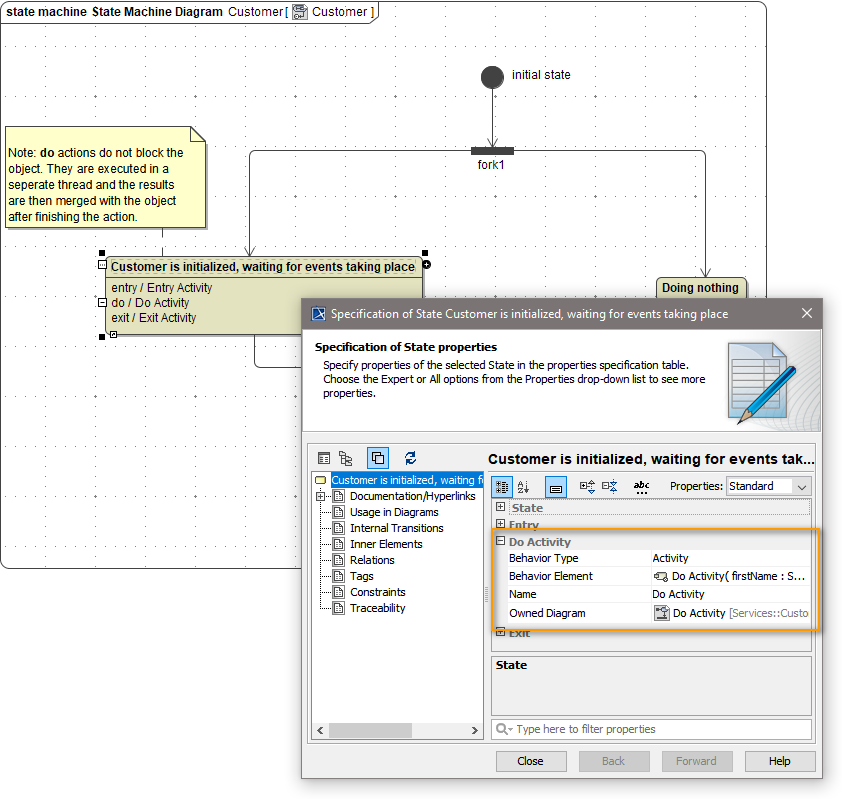
As a downside, due to the concurrency, there are limitations to the manipulation of the persisted objects. After a do activity, changes to the self-object are not automatically persisted. To modify contents of the persisted object, the do activity has to return the corresponding attributes as output parameters. For example, the following do activity returns the parameters firstName and lastName (this activity diagram can be found in the pstateForks.xml example):
Figure: Do Activity
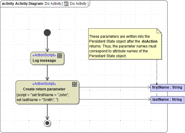
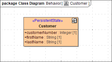
The <<PersistentState>> class owning this do activity has two attributes having the same name and type (see following class diagram). Therefore, after finishing the do activity, these two parameters get synchronized with the persistent state object attributes firstName and lastName.
Figure: Class to Be Synchronized After Do Activity
The do activity is defined in the Do Activity compartment of the state specification dialog.
- Behavior Type needs to be set to Activity.
- Then, select or create the implementing activity in the Behavior Element field.
For example:
Example File (Builder project Advanced Modeling/PState):
| <your example path>\Advanced Modeling\PState\uml\pstateForks.xml |
Handling Unhandled Errors
If an error occurs in an activity diagram that is not being caught there, the state machine rolls back to the last action. In case of exit-, entry-, or transition actions, this is the source state. In the case of do-actions, this is the current state. However, it is possible to define a default error handler.
Example File (Builder project Advanced Modeling/PState):
| <your example path>\Advanced Modeling\PState\uml\pstatePurchaseOrder.xml |
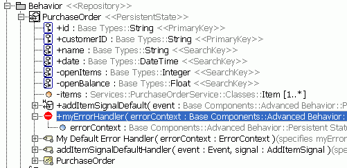
The default error handler is defined as an operation having the stereotype <<PersistentStateErrorHandler>>. In the following example, operation myErrorHandler is always invoked automatically if an unhandled error occurs.
Figure: Default Error Handler in Content Tree
Operation myErrorHandler has exactly one input parameter of type ErrorContext named errorContext. Its attributes are:
| Attribute | Description | Values | |
|---|---|---|---|
| actionType | actionType specifies where the error occurred. | entry | Error occurred in an entry behavior. |
| exit | Error occurred in an exit behavior. | ||
| do | Error occurred in a do activity. | ||
| transition | Error occurred on a transition. | ||
| guard | Error occurred on a guarded transition. | ||
| actionID | These ids basically consist of the action/state name plus a unique identifier. If special characters and spaces are used in the action name, they will be skipped during generation of the id.Technically spoken, it must be an NMTOKEN. | ||
| sourceStateID | |||
| targetStateID | |||
The activity diagram implementing the default error handler in the pstatePurchaseOrder.xml example is depicted in the next figure. Basically, it logs the last error and throws a new one. It is important to note that the default error handler is very similar to a catch all after each action. This has two consequences:
- First, it allows to get the last error using the built-in getError() operation.
- Second, if no new exception is thrown in the error handler, the state machine will proceed with processing the next action. Only exception: the error occurs within a choice (see note further below). Thus, in this example we will throw another exception in the error handler.
Figure: Throwing the Exception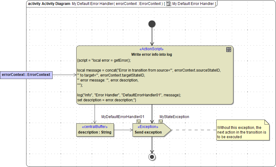
Final State
The final state - the bull's eye - denotes the end of the object's life-cycle. There can be more than one final state or none at all.
A persisted object is destroyed when a final state is reached. Before the final destruction, any default handler for pending, non-delivered signals will be executed.
No final state means that the persistent object will stay in the state database forever. This could lead to performance degradation, thus, we recommend having always transitions to the final state, for example by using time events to implement a time-out behavior. If it is required to save the object state permanently before destroying it, just use the event handler of the last transition to implement this behavior.
Choice
The choice state is equivalent to the decision element of activity diagrams. Guards on the outgoing transitions will be checked until one returns true. Only this transition will then be executed.
Choice is a pseudo state. When a transition enters a choice element, guards will be evaluated and the matching outgoing transition will be executed within the same transactional context. A rollback will go back to the state before the choice. The only values accessible within transition guards starting from a choice are the attributes of the Persistent State object. They are accessed using the keyword self, for example:
Figure: Choice Pseudo State
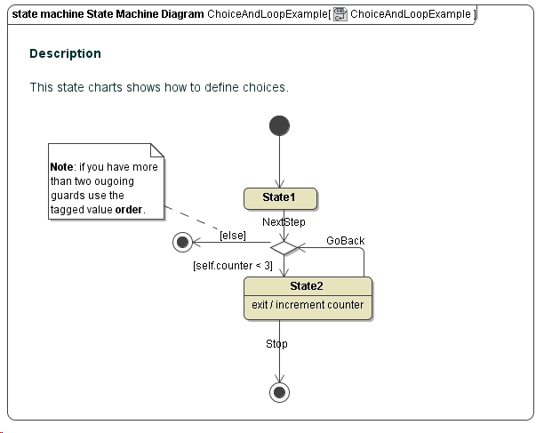
If there are more than two transitions starting from the choice state, the order tag of the <<E2EOrdered>> stereotype has to be used to order the evaluation of the expressions.
Example File (Builder project Advanced Modeling/PState):
| <your example path>\Advanced Modeling\PState\uml\pstateChoices.xml |
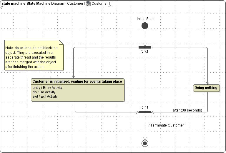
Fork
The fork state splits the execution into multiple parallel paths. All outgoing transitions will be taken and thereafter an object will be in multiple states at the same time.
Fork is a pseudo state. When a transition enters a fork, all outgoing transitions will be executed within the same transactional context. A rollback will go back to the state before the fork.
Figure: Fork & Join States
Example File (Builder project Advanced Modeling/PState):
| <your example path>\Advanced Modeling\PState\uml\pstateForks.xml |
Join
The join state is the opposite of the fork state. It does join multiple parallel paths back into one. Unlike the choice state, all incoming transitions have to be executed before the outgoing transition is processed; this is also called AND join. For an example see figure Fork & Join States.
Unlike fork, join is not a pseudo state. After a transition enters a join state, the persisted object will stay in this state until all other transitions arrive. After the last transition arrived, an internal asynchronous signal will be created that tells the object to leave the join state. If the outgoing transition is rolled back, the object stays in the join state.
Example File (Builder project Advanced Modeling/PState):
| <your example path>\Advanced Modeling\PState\uml\pstateForks.xml |
Composite and Submachine States
The composite state is a super state that encompasses one or multiple sub states. A composite state can be thought of as a bracket around its sub states.
In itself, a composite state behaves like a regular state. It can have entry and exit behaviors that are executed when the state is entered and left. Even though it does not support do activities, the state machine diagram drawn within the boundaries of a composite state acts like a do activity.
Transitions leaving from a composite state will terminate any embedded sub states. This can be useful to define signals or time-outs that interrupt a process resembled by the sub states. Be aware, that in such a case only the exit behavior of the composite state itself will be called.
A completion event (no specified trigger or a timeout of 0 seconds) is only triggered when the state machine defined within reaches its final state. When an embedded state machine terminates, but only triggered transitions exit the composite state, the persistent state object will stay in this composite state until one of the triggers fires.
Using entry point and exit point pseudo states, the modeler can define different points through which a composite state can be entered or left. A composite state can have multiple entry and exit points.
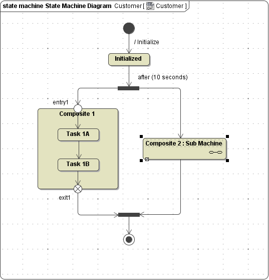
The submachine state is primarily used to encapsulate and hide complexity behind single states. In this regard, it is similar to sub activity in UML activity diagrams.
The behavior of the submachine state is the same as with composite state described above. The following examples shows both, a composite- and a submachine state:
Figure: Composite- and Submachine States
Also with submachine states it is possible to control their entry and exit points, though they are called connection points.
For example, the state machine in the next figure calls a submachine using two different connection points.
Figure: Definition of Connection Points When Calling a Submachine
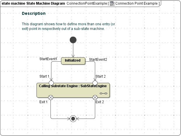
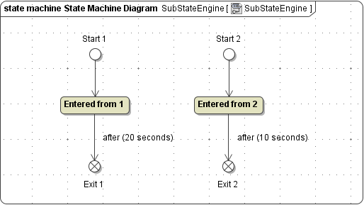
The connection points are directly linked to Entry- and Exit Points in the called submachine.
Figure: Definition of Connection Points When Calling a Submachine
Of course, the entry and exit points may or may not be paired.
Example File (Builder project Advanced Modeling/PState):![]()
<your example path>\Advanced Modeling\PState\uml\pstateSubstate.xml
<your example path>\Advanced Modeling\PState\uml\pstateConnectionPoints.xml
Entry and Exit Point
Entry and exit points are used in conjunction with Composite and Submachine states. See the previous sections for details.
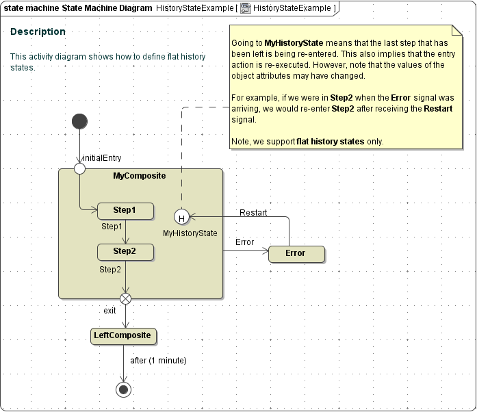
History State
In UML, it is possible to define states within composites that remember the last state the composite had before it has been left. These states are called history states. For example, in the following state diagram the composite MyComposite is in state Step1 or Step2. When the Error signal arrives while the state machine is in Step2, the history state remembers this. Then, if the composite is re-entered receiving the Restart signal, the history state will trigger the re-entry of Step2 - implying the re-execution of the entry action of Step2.
Figure: History States
Example File (Builder project Advanced Modeling/PState):![]()
<your example path>\Advanced Modeling\PState\uml\pstateHistoryStates.xml
Overview
Content Tools