
In UML, activity diagrams are used to model the behavior of operations, classes, or use cases. This chapter describes how activity diagrams are used to model the behavior of operations. Activity diagrams describe actions that shall be executed in a specific order (control flow) and how data is being transformed (object flow).
There are several types of actions. For the implementation of operations, the Bridge supports the following kinds of activities:
- Actions are used to describe actions applied to objects or the environment. They may contain so-called action scripts, or can be stereotyped signaling a special kind of an action. For instance, <<SQLAdapter>> actions apply actions to SQL databases.
- Call Behavior Actions give a link to other activity diagrams. Therefore, it is possible to decompose the behavioral logic into smaller units of activities.
- Call Operation Actions can be used to call class operations encapsulating specific behaviors.
Besides designing the control flow with actions, there are objects that are part of defining an object flow in an activity. An object flow models the flow of values to or from object nodes. Objects may be input and output of single actions, or input and output of activities.
Activities and Activity Diagrams
An activity ( ![]() ) is created upon creation of an activity diagram (
) is created upon creation of an activity diagram ( ![]() ). It is containing all UML elements that are used in the activity diagrams of this activity. An activity can have several activity diagrams, each of them representing a special view on the activity (for instance, error handling could be placed in a second activity diagram). However, in this course, only one activity diagram per activity is defined.
). It is containing all UML elements that are used in the activity diagrams of this activity. An activity can have several activity diagrams, each of them representing a special view on the activity (for instance, error handling could be placed in a second activity diagram). However, in this course, only one activity diagram per activity is defined.
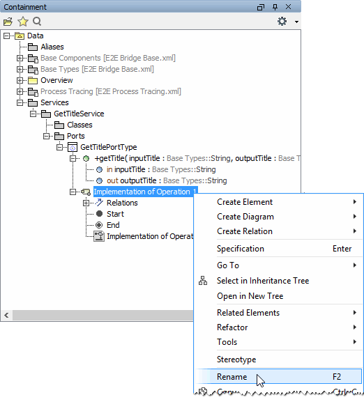
You will start by renaming the pre-defined activity and activity diagram.
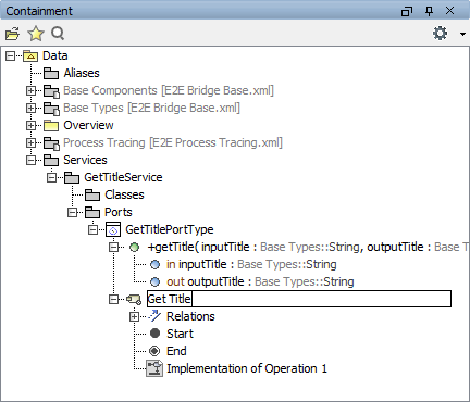
| Expand the activity node Implementation of Operation 1 in the containment tree and rename the activity. |
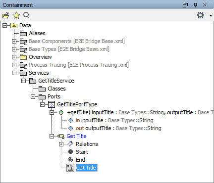
| The name of the activity respectively the activity diagram should always correspond to the name of the operation it is specifying. Assign the name Get Title. |
|
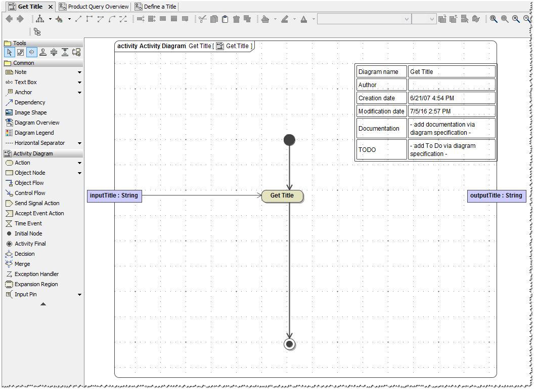
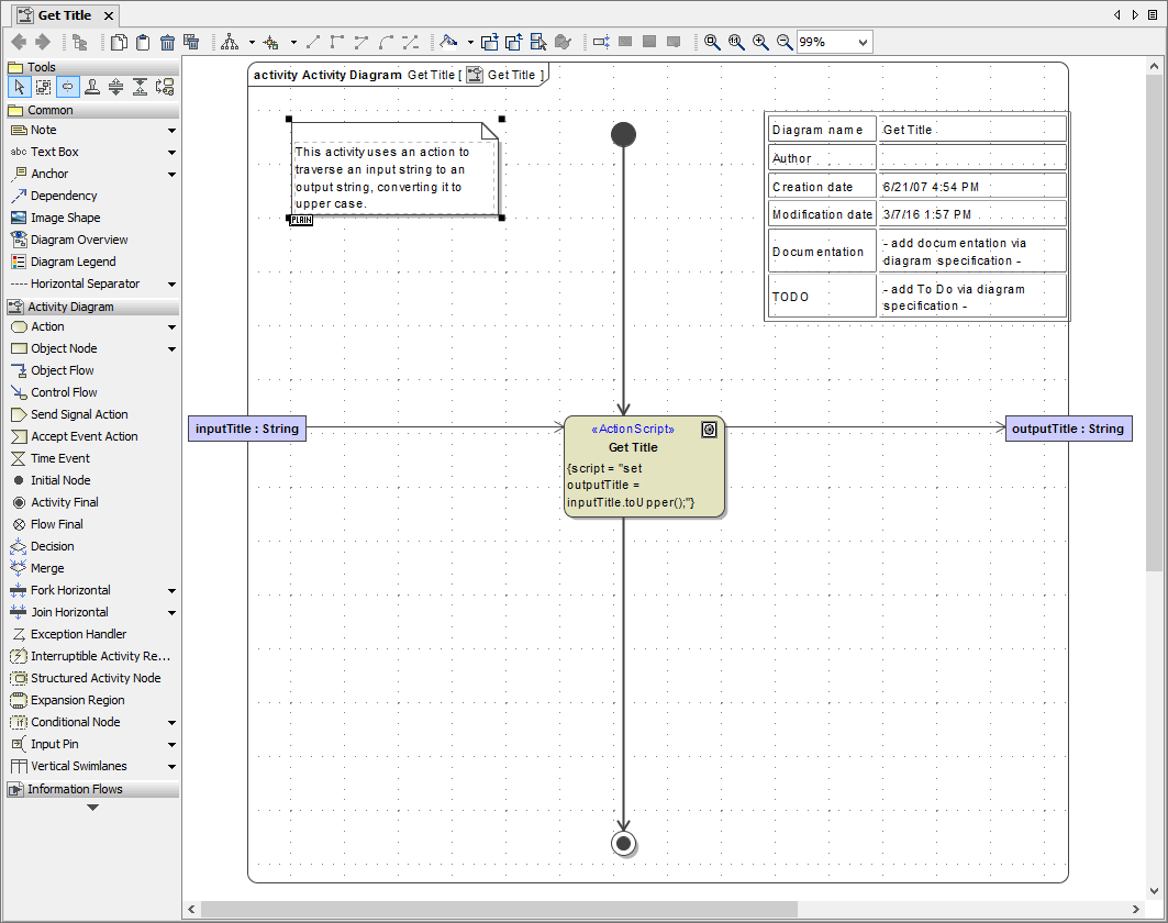
Double-click the activity diagram in the containment tree in order to open it. The predefined activity diagram already contains some UML elements in the diagram pane.
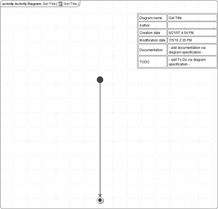
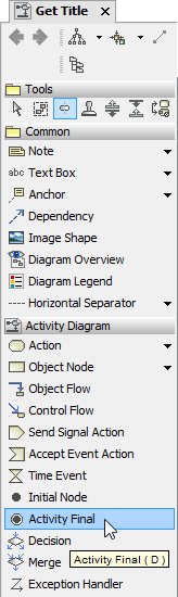
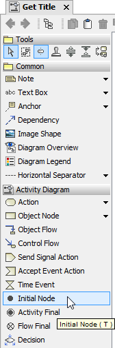
Each activity diagram needs a starting point called initial node. The initial node icon defines the start of the activity behind the operation of a port type. An activity final node defines the end of an activity. In the predefined activity diagram, the two nodes are already connected with a control flow.
Initial Node and Activity Final icons can be found in the diagram toolbar:
|
|  |
Adding Parameters to the Activity
An object is an instance of a class. It stores data that can be modified within activities. Objects may originate outside of the context of an activity – in other words, they are input parameters to the activity. On the other side, activities may produce objects that are used as output. Output objects can be used as input of another action within the same context (the same activity diagram), or they can be passed as output parameters to an outside context, which can be a calling activity or a port type operation.
In the following steps you will define the input and output parameters of the activity implementing the port type operation getTitle. These parameters must have the same name, type, and direction (in, out, or inout) as the operation parameters. The most efficient way is to copy the parameters in the containment tree from the operation node to the activity node.
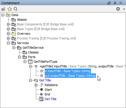
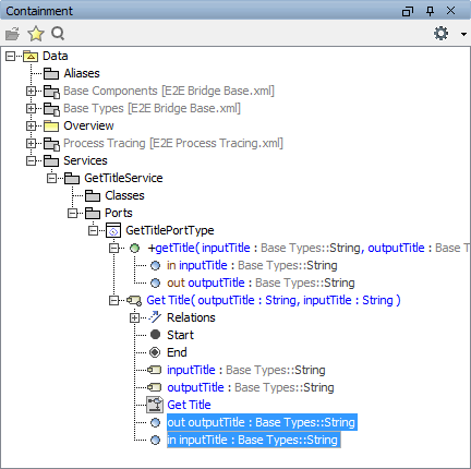
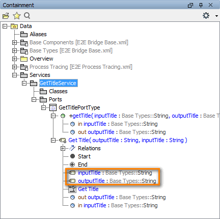
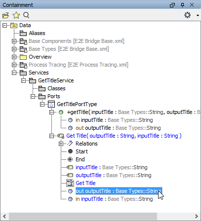
| Open the operation getTitle in the containment tree and select the two parameters inputTitle and outputTitle. |
| Next, hold down the Ctrl key of your keyboard and drag the two parameters over the activity node. Holding down the Ctrl key tells MagicDraw to make a copy of the parameters instead of moving them from the operation node to the activity node. A +-sign attached to the cursor arrow indicates the copy action. |
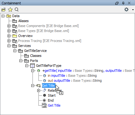
| Release the mouse button when the activity node Get Title is active. MagicDraw will create an exact copy of the operation parameters within the activity. |
Now, you will add the two parameters to the activity diagram in the diagram pane to model the object flow. For this purpose, UML elements called Activity Parameter Nodes are used. Each activity parameter node works as container of a parameter. When they are drawn in the activity diagram, they have a different color than normal object nodes to indicate that these nodes contain activity parameters.
In order to visualize if an activity parameter node contains an input or an output parameter, you can place them on the left or right side of the diagram frame. The left side corresponds to input, the right side to output.
| When copying the parameters from the operation to the activity, you may have noticed that two activity parameter nodes have been created automatically (see highlighted area on the left). They have the same names as the corresponding parameters. |
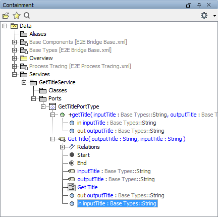
| Select the parameter inputTitle in the containment tree. |
As it is an input parameter, drag the selected parameter to the left border of the diagram frame until the diagram frame gets surrounded by a blue rectangle. 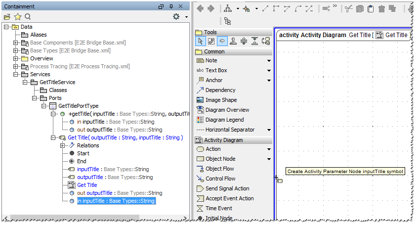 Release the mouse button.
| |
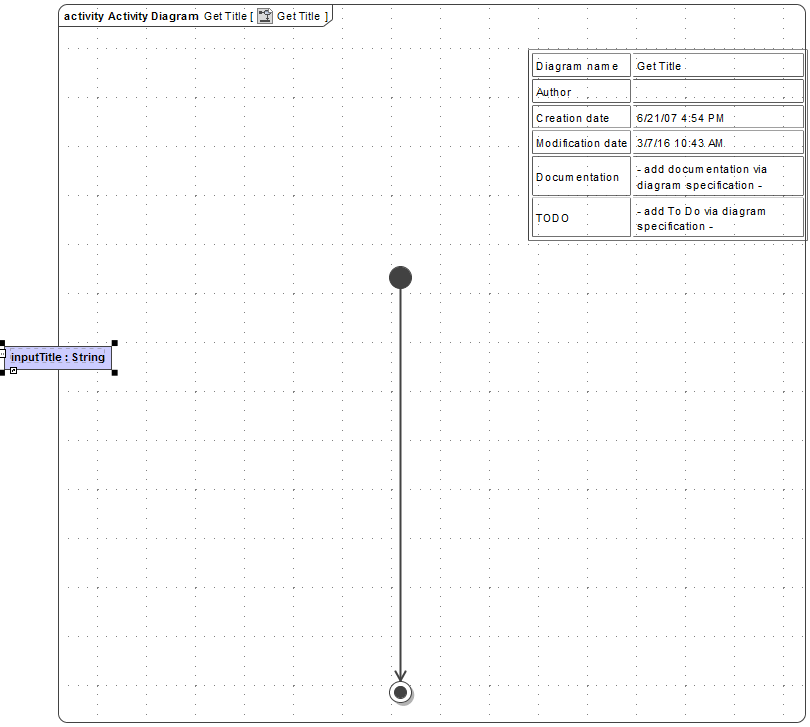
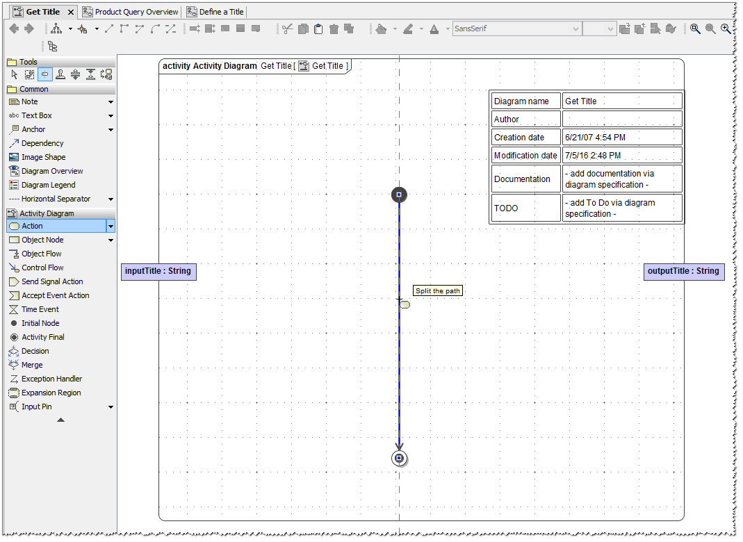
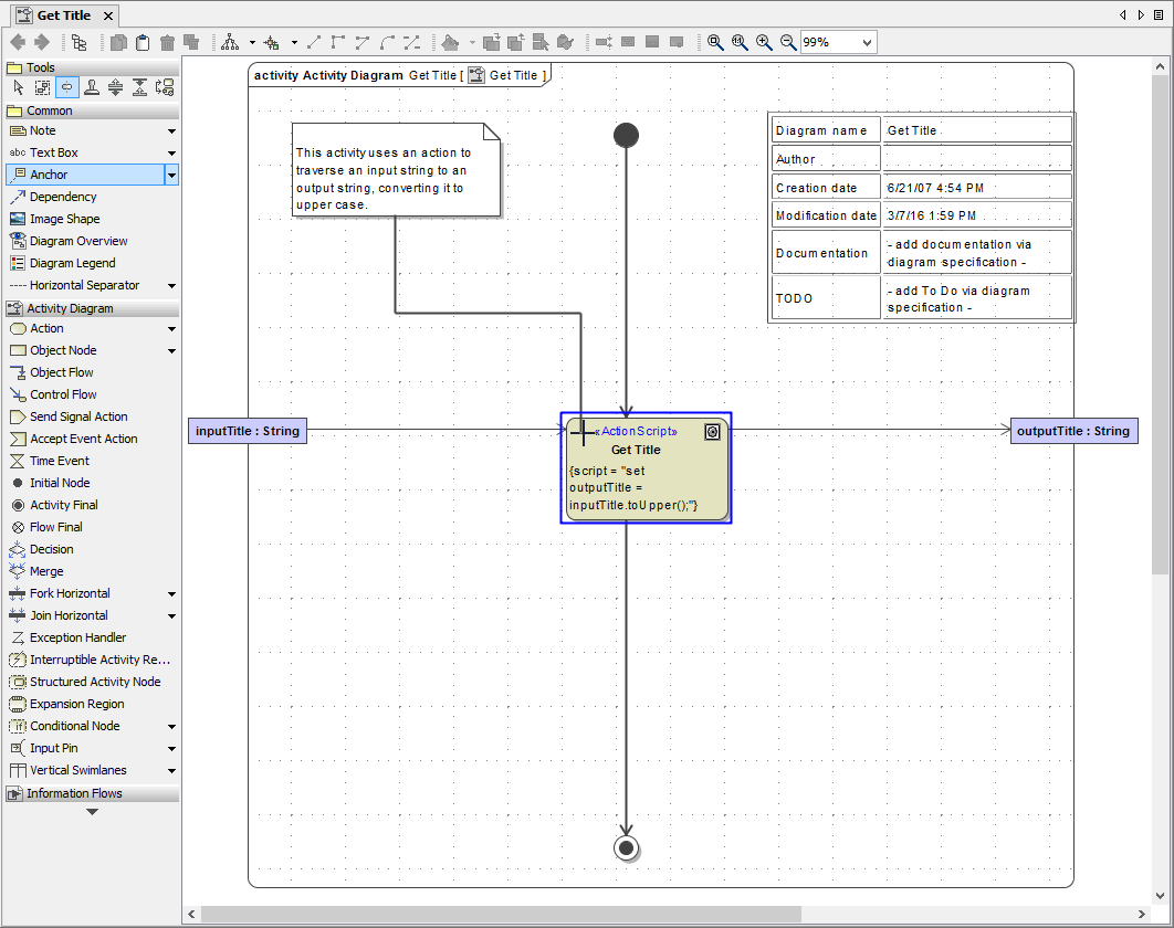
The input activity parameter node has been drawn in the activity diagram and shows the name and type of the parameter it is containing. On the right side of the colon, the type of the parameter (String) is displayed.
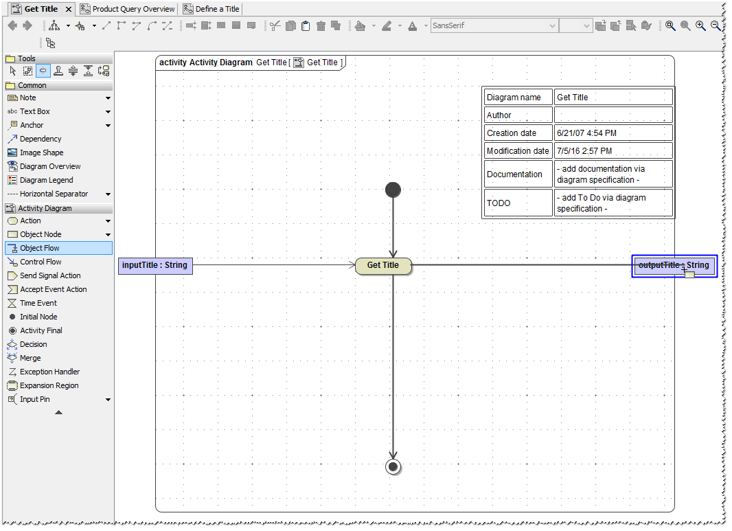
| Now add the output parameter to the activity diagram. Select the parameter outputTitle in the containment tree. |
As it is an output parameter, drag the selected parameter to the right border of the diagram frame until the diagram frame gets surrounded by a blue rectangle.
| |
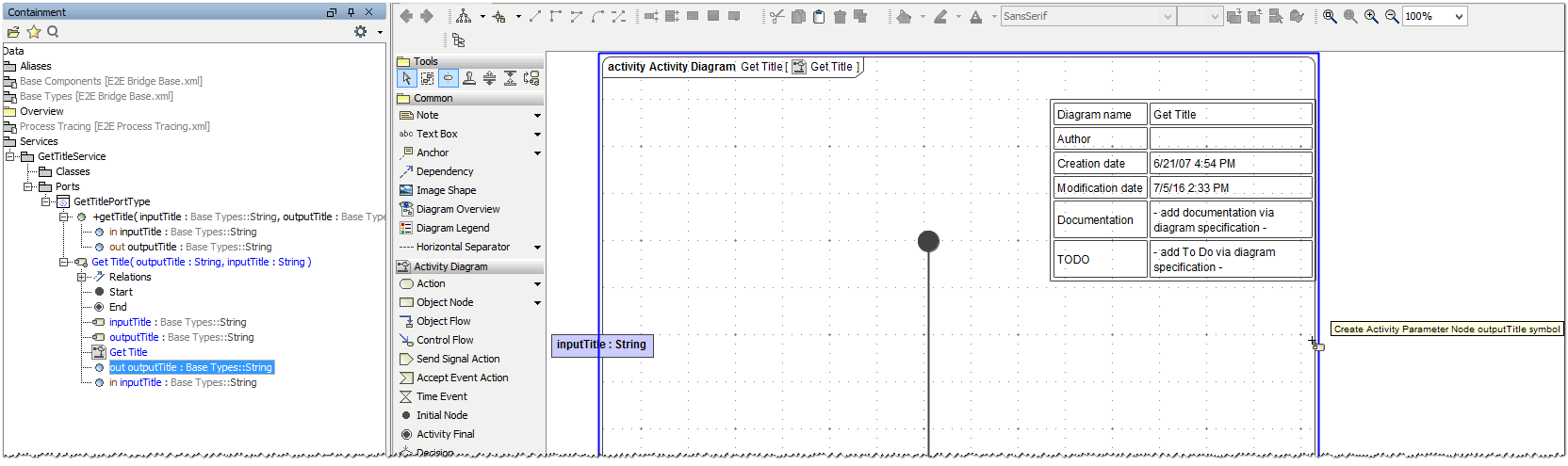
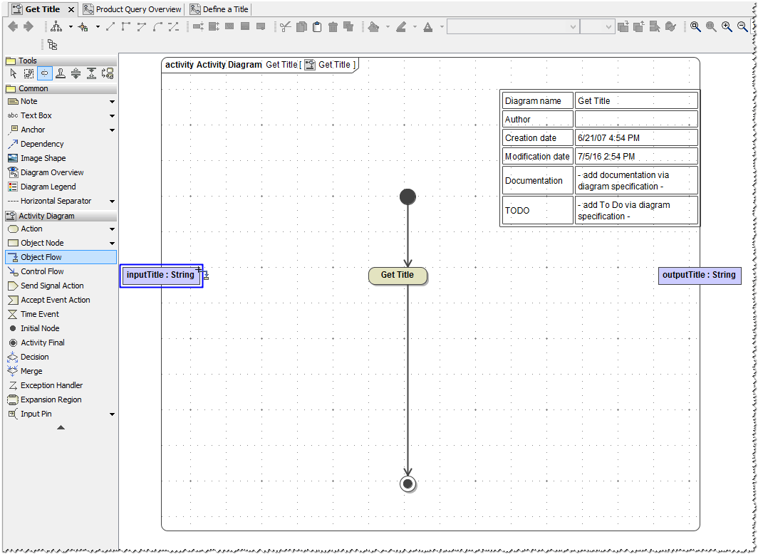
Release the mouse button. The output activity parameter node has been drawn in the activity diagram and is displaying the name and type of the parameter it is containing.
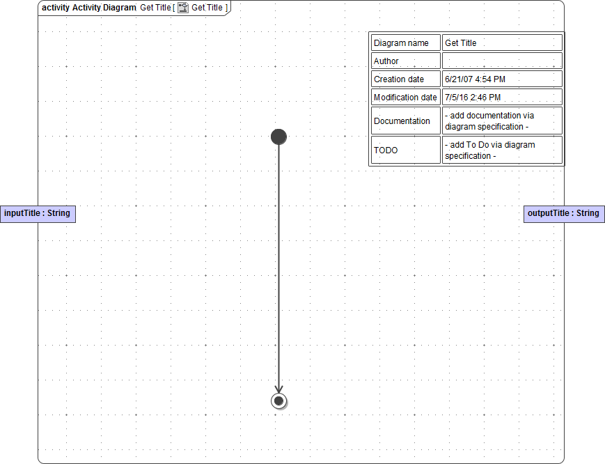
Designing the Control Flow
Initial node, activity final node, and the two activity parameter nodes inputTitle and outputTitle have been defined so far, but no action node yet.
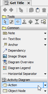
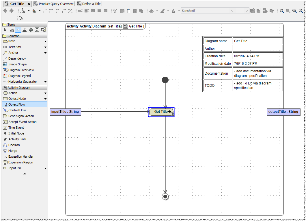
| You will now add an action to the activity diagram by selecting the Action icon from the diagram toolbar. |
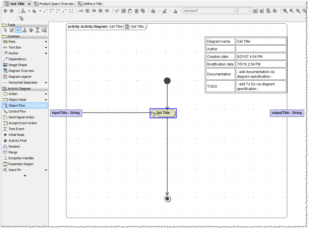
| The most efficient way to insert an action node in an existing control flow is to drag it onto this control flow, which will be split by MagicDraw automatically without the need to reconnect the initial node, the action node, and the activity final node manually. Drag the action node onto the control flow, which connects the initial node and the activity final node. As soon as you move the +-sign of the cursor over the control flow, the blue helper grid line appears. Release the mouse button to insert the action node. |
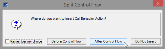
| In the following dialog, click the button After Control Flow. The action node is now integrated into the control flow. You can place any action with the described method into control flows. |
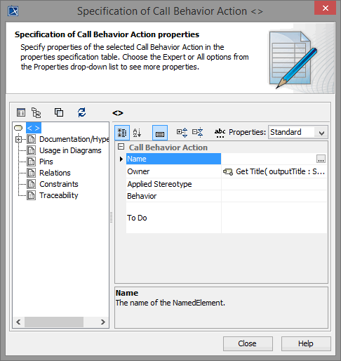
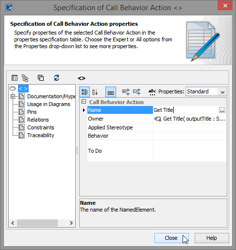
| Double-click the action node to open its specification dialog. |
| Name the action Get Title and close the dialog. |
This action currently does nothing. Before you add action script to the action in order to implement some behavior, you need to complete the object flow.
Designing the Object Flow
Object flows capture how objects participate in activities and how they are affected by the activities. Objects or data are passed along the object flow.
In activity diagrams, object flows are represented by slightly thinner lines than control flows. They model the flow of values to or from object nodes. Object nodes may be input and output of single actions, or input and output of activity diagrams.
- The object inputTitle is input of the activity (the input parameter is passed from the caller of the activity diagram - the assigned port type operation). The object inputTitle will also be the input of the single action Get Title.
- The object outputTitle will be the output of the action Get Title. The object outputTitle is also output of the activity diagram (the output parameter is passed to the caller of the activity diagram, which is the assigned port type operation).
You will now connect the objects inputTitle and outputTitle with the action Get Title.
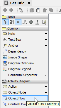
| Select the Object Flow icon from the diagram toolbar. |
| Move the mouse cursor over the activity parameter node inputTitle and click it when the blue activation frame appears. |
| Move the cursor over the action node Get Title and click it to connect the object flow. |
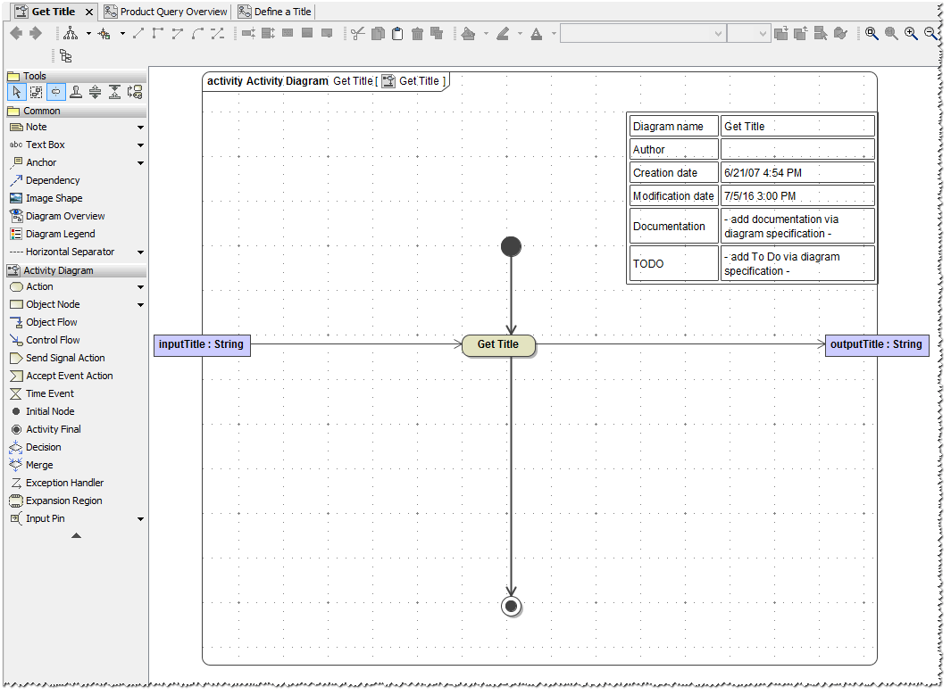
| Now, the object flow connects the activity parameter node and the action node. The direction of the arrow indicates that the action node receives the input string inputTitle. |
| Now you will draw the other object flow from the action node Get Title to the output activity parameter node outputTitle. Select the Object Flow icon from the diagram toolbar. Move the mouse cursor over the action node Get Title and click it when the blue activation frame appears. |
| Move the cursor over the output activity parameter node outputTitle and click it as soon as the blue activation frame appears. |
| Drawing the object flow in this direction indicates that the action creates the output string outputTitle. The object is passed to the caller of the activity diagram, which is the assigned port type operation. |
The action Get Title currently does nothing. In the next step, you will add action script to the action in order to implement some behavior.
Save ![]() the UML model.
the UML model.
Using E2E Action Language
For implementing behavior in actions, the Bridge provides the E2E Action Language (EAL), which implements parts of the Action Semantics UML Extensions. This language is used in a script like fashion in the action script part of the actions. The E2E Action Script Editor supports the E2E Action Language and helps you to quickly create syntactical correct action script statements.
Remember that the Web service will take a string as input and pass the output back to the client. In the next step, the action Get Title will "learn" how to transform the input string to upper case and how to assign it to the output object by using action script.
Click the action node Get Title with the right mouse button, and select the menu item E2E Action Script Editor in the context menu.
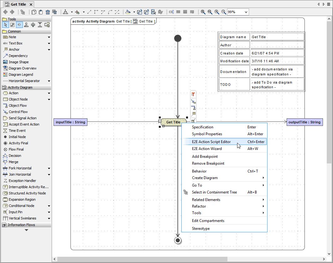
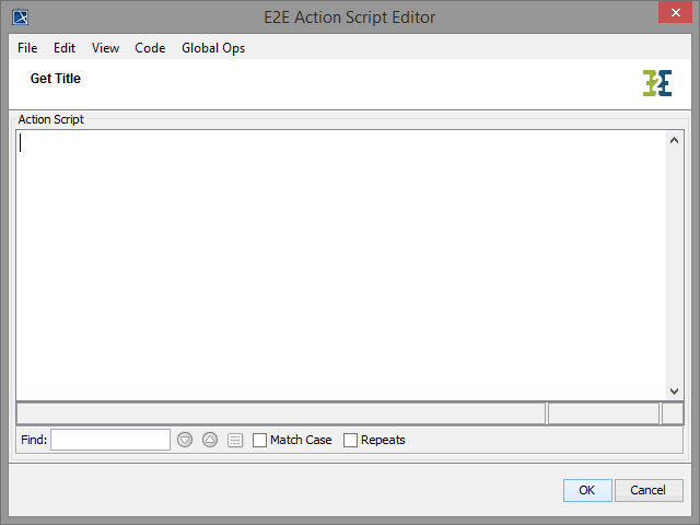
| The E2E Action Script Editor dialog opens. |
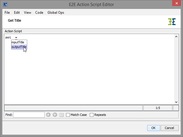
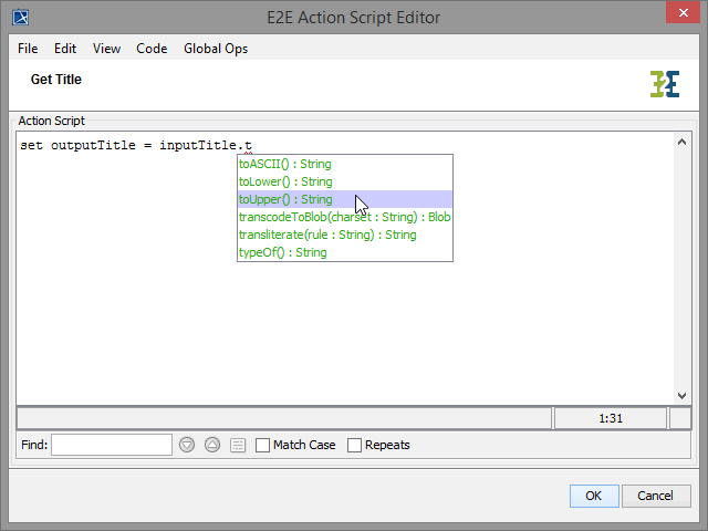
| Operations, functions, and macros of the action language are displayed in blue . To create the action script statement, start by typing the Click the entry for the object outputTitle in order to select it. Alternatively, use the arrow keys to mark it and press the Enter key to select it. |
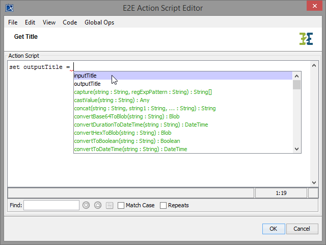
| After selecting the output object, a space and an equal sign (=) are added automatically to the statement. Press the End key to jump to the end of the line and press Ctrl - Space to open the suggestion list again. Select the object inputTitle by clicking it or pressing the Enter key. |
| All letters of the input string need to be converted to upper case. This will be done by using the toUpper() operation of the base class String. As the object inputTitle is of type String, the Action Script Editor will provide all possible operations. Type ".". The suggestion list containing all attributes and valid operations for object inputTitle will appear. Type "t" to filter the suggestion list and select method |
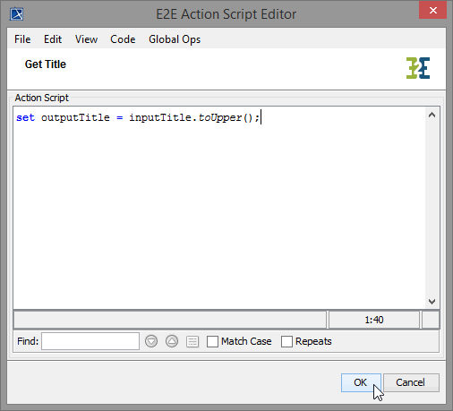
| Every action script statement needs to be ended with a semicolon (;). The statement for assigning the value of the converted input object to the output object is completed. Add a semicolon and click the OK button or press Ctrl - Enter to save the action script and close the editor. |
|
Often, it is helpful to describe what the statements will do. You can comment one or more lines for this purpose. Each comment line in the action script is preceded by two slashes (//).
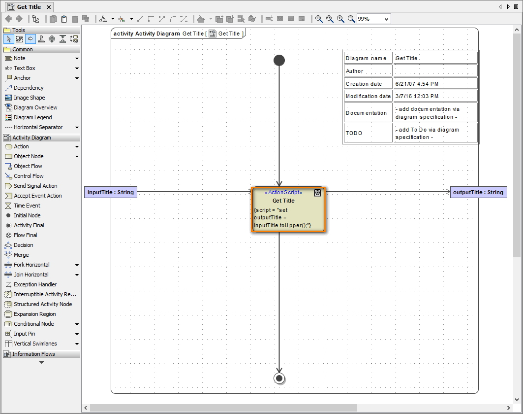
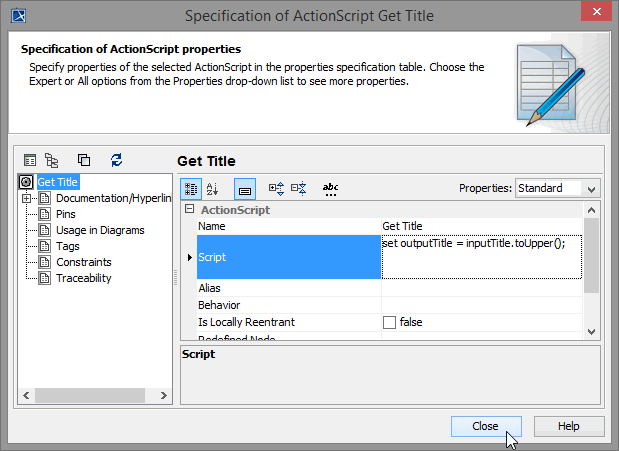
| If you double-click the action node Get Title, the action's specification dialog will open. The action script statement you just entered in the Action Script Editor is shown in the Script field. You could also enter or modify the action script here. However, no help is provided to create syntactical correct action script statements. Furthermore, no suggestion lists are displayed, which help you to enter action script quickly. |
Save ![]() the UML model.
the UML model.
Creating Notes
Often it is necessary to annotate the activity diagram with notes in order to document the control flow, describe the activities, or enter other useful information.
The note can be used for text based documentation. You can also apply HTML formatting to the text you entered.
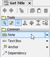
Select the Note icon from the diagram toolbar and place it somewhere in the activity diagram.
The note is already in editing mode. If not, switch to editing mode by clicking into the note:
| |
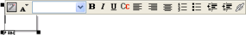
An HTML toolbar floating above the note is activated. You can use it to format text or create hyperlinks to other diagrams in the UML model.
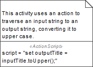
Write a descriptive text into the field, e.g. This activity uses an action to traverse an input string to an output string, converting it to upper case. Press Ctrl - Enter or click outside the note to leave the editing mode. If Autosize is switched on, you can switch off the autosize feature in the context menu of the note, if you want to resize it manually (you may need to expand the context menu to see all menu items). Use the shape handles to resize the note, then.
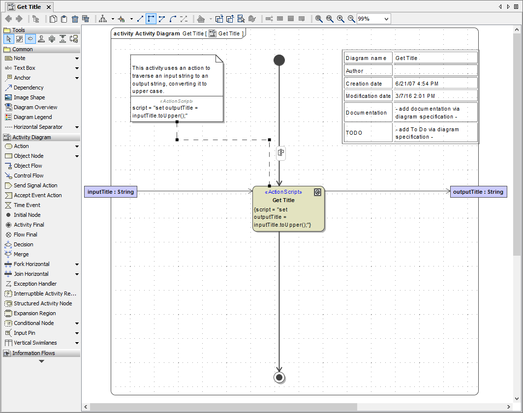
By using anchors, you can attach the note to any UML element in the activity diagram. Select the Anchor icon ![]() from the smart manipulation toolbar of the note. You can use this icon for any UML element in the activity diagram. Move the anchor over the UML element you want to attach the note to. When the blue activation frame appears, click to connect the anchor to the UML element.
from the smart manipulation toolbar of the note. You can use this icon for any UML element in the activity diagram. Move the anchor over the UML element you want to attach the note to. When the blue activation frame appears, click to connect the anchor to the UML element.
The note is now connected to the action node with a connecting line (anchor).
| As shown on the left, the tagged value script is displayed in the lower compartment of the note. |
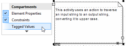
| You can stop showing tagged values in the note by deselecting the option Tagged Values in its context menu which opens when clicking at the |

Save ![]() the UML model.
the UML model.

On this Page:
Overview
Content Tools