Adding Elements to the Diagram Pane
You have two options to add an element to the diagram pane:
-
Using the elements toolbar.
-
Using the context menu.
Drag the element you want to create from the toolbar and drop it on the diagram pane:
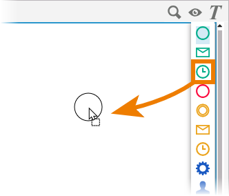
Another way to create a bpmn element is to click on the element in the toolbar, switch to the editor and click again. To cancel the operation, press the Esc key.
As soon as you have created a first element, you can also use the element context menu to create further elements. Click on an element or hover over the active element to open the context menu:
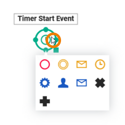
Start events can only be created via the elements toolbar.
If you mark an element on the diagram pane before you create a new element, a relation is automatically created between both elements:

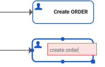
Double click the name of the element to enable edit mode and change the content:
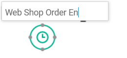
When creating new elements, respect the restrictions for element names. Your input is validated, but the validation is case insensitive:
Restrictions on Element Names
BPMN element names must be unique within one BPMN model. During name validation spaces and underscores are treated the same, e.g. Step 1 and Step_1 are duplicate names.
In addition, the following name restrictions apply:
Element names...
-
... must not be empty.
-
... must not start with numbers.
-
... must not end with a period (.).
-
... must not contain one of the following characters: <, >, :, ", /, \, |, ?, *
-
Furthermore, the following strings must not be used as element names: CON, PRN, AUX, NUL, COM1, COM2, COM3, COM4, COM5, COM6, COM7, COM8, COM9, LPT1, LPT2, LPT3, LPT4, LPT5, LPT6, LPT7, LPT8, LPT9.
Open the Styling panel to change the formatting of an element:

Refer to page Styling BPMN Elements for detailed information.
Creating Relations on the Diagram Pane
You need to draw relations from one element to another to create an executable process. If you activate an element on the canvas before you create a new element, a relation is automatically created:
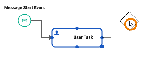
Pressing the Esc key cancels the drawing of a relation:
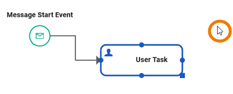
If you press Del or the backspace key directly after the creation process, the relation and the active element are deleted:

Click on a relation to select it. A selected relation is thicker and shows junctions:
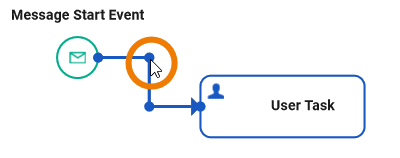
When creating a relation, the easiest path will be chosen by default. This may not always be desired. That's why the route of the relation can be altered by the modeler. Use the junctions to adjust the selected relation:

Deleting Elements from the Diagram Pane
To remove an element from the digram pane, right click on the element to open the context menu and use option Delete:
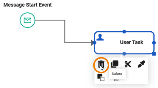
You can also use the Del or backspace key to delete an element.
If you want to remove a relation, open the context menu on the relation and use Delete:
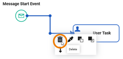
You can also select the relation and use the Del or backspace keys on your keyboard.
This also applies if you select several elements at once:

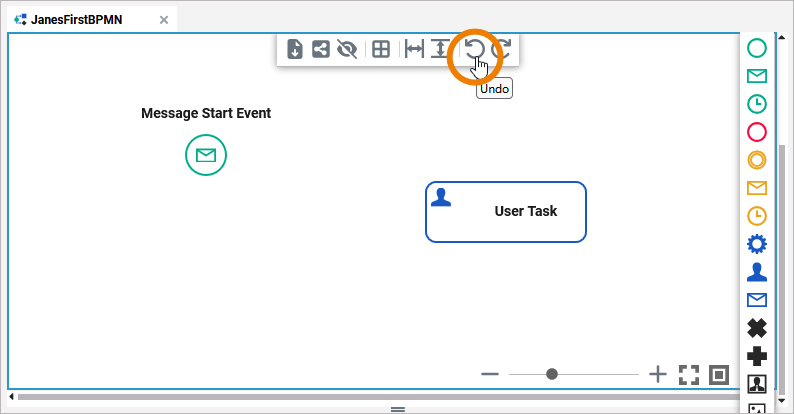
Deleting elements is an action that can be undone using the Undo option in the model toolbar:
