The E2E Builder does not allow multiple component diagrams within the same service model. If you want to specify multiple deployments for the same service, we recommend to proceed as follows:
-
Extract the service implementation.
Create an UML model having no component diagram, that only contains the service implementation. Share the packages of this model you want to reuse. -
Create a separate model for each desired deployment.
For each of the different deployments, create a separate UML model and import the service implementation as a module. Then, add a component diagram to this model reflecting the desired deployment.
The JMS examples are build this way:
Extracting the Service Implementation
Reducing the Service to the Implementation Only
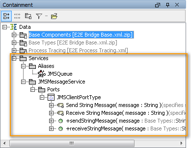
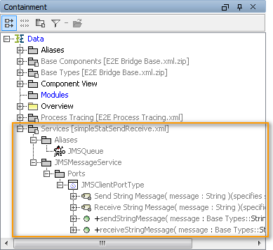
Create an UML model without any component diagram, containing only the service implementation and other needed elements. In case of the example, this is a JMS alias. We recommend to put all needed elements of the module in the same package (e.g. Services).
Figure: Containment Tree of the Service Implementation - First Step
Sharing the Needed Packages
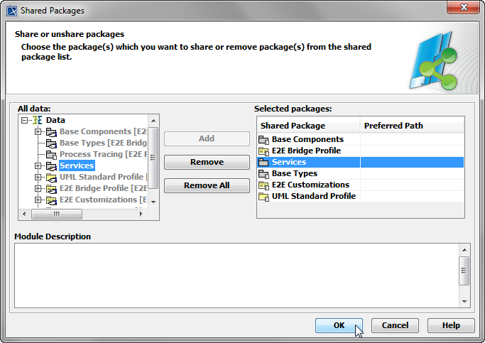
Share the needed package(s), so it can be used, when the service will be imported as a module. Select File > Share Packages from the menu.
Select the package(s) you want to share (Services in this case) and click Add to add them to the list of shared packages. Click OK:
You may be asked then, if you want to check for cyclic dependencies on modules. It would be wise to do so, but this depends on the complexity of your service.
While creating the shares, MagicDraw will add automatic shares for some E2E Bridge packages.
Save ![]()
Importing the Module
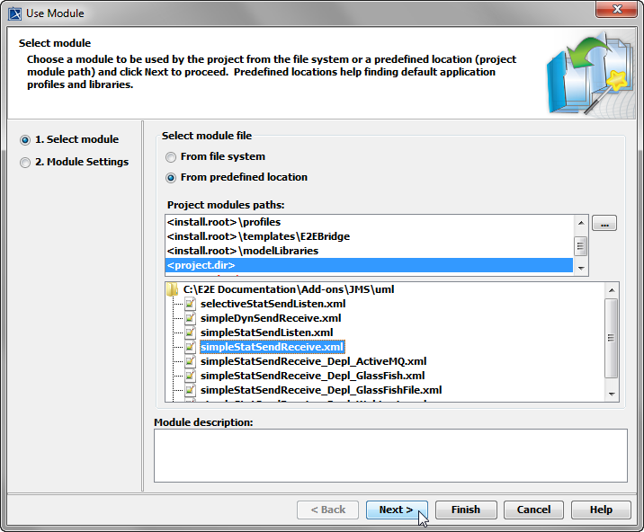
Create a new UML model from E2E Bridge template. Select File > Use Module from the menu.
|
Browse to the location of the module you want to use, e.g. <project dir>/simpleStatSendReceive.xml. Click Next, if you want to change settings of the imported module.
|
|
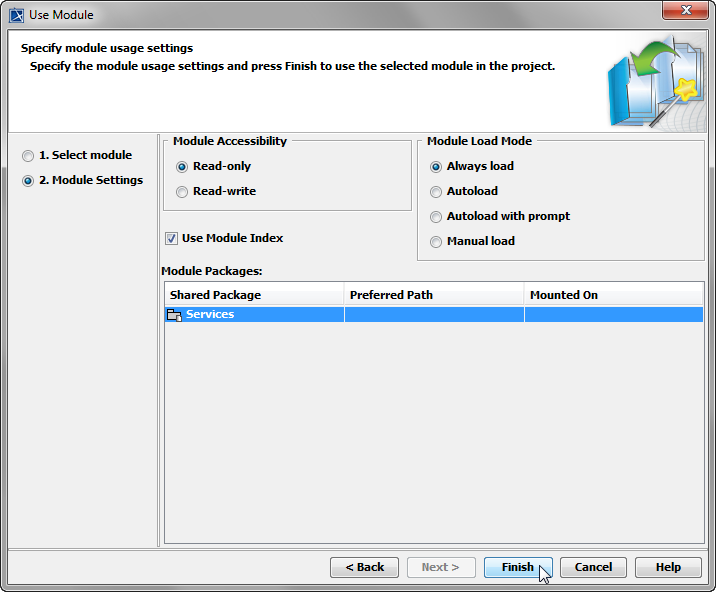
In the next step, you may change some settings that will be applied during the import. Click Finish to import the module. |
|
If you did not change any settings during the import, you now have imported the service implementation as a read-only module. |
|
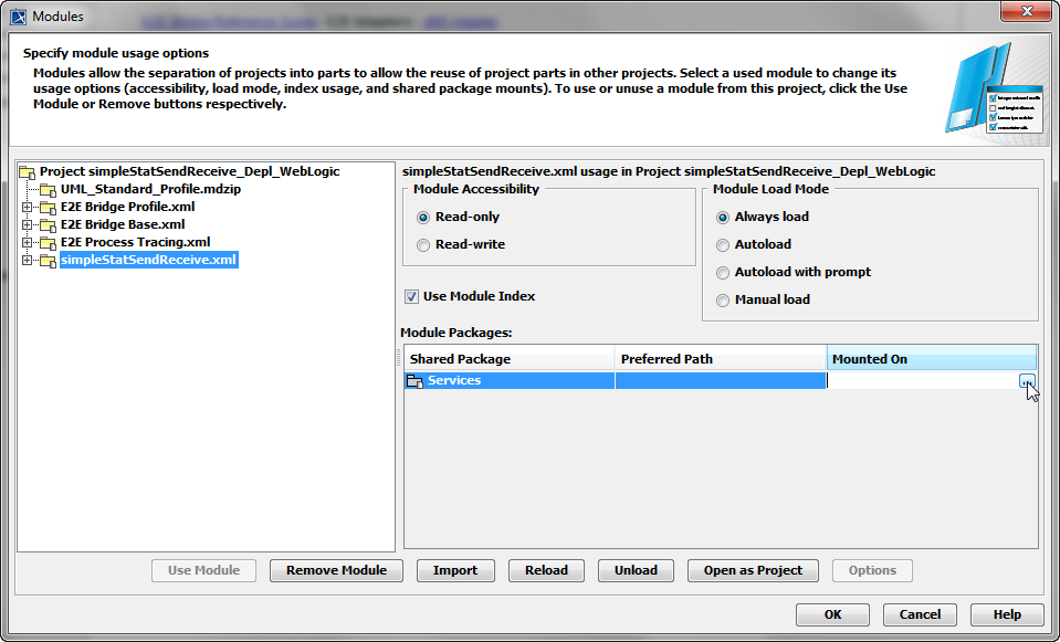
We recommend to mount all modules to a subordinate package Modules. To do this, select Options > Modules from the menu and select the module you just imported.
Click OK. |
Now you can continue by creating a component diagram reflecting the desired deployment.
Creating a Component Diagram Reflecting the Deployment
Start the Components Wizard and create a component diagram as described in Creating a Component Diagram.
It is not possible to specify the usage of the JMS alias via the Components Wizard. In case of the example that means, that you have to add the JMS alias manually to the component diagram.
|
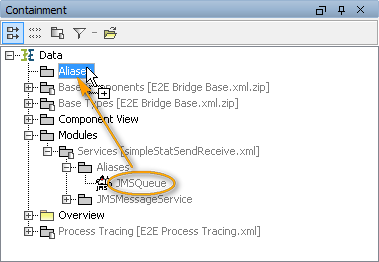
Do not use the imported alias (JMSQueue in this case), but copy the imported alias to package Aliases in the containment tree. Do not change the name of the alias, because the imported service implementation is referring to an alias with this name. |
|
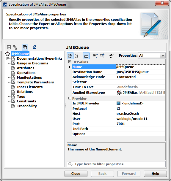
The copied alias is not read-only. Apply all needed JMS settings to it. |
|
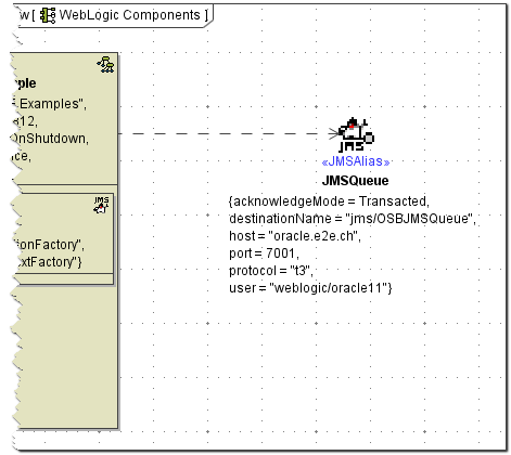
Add the copied alias to the component diagram. To do this, drag and drop the alias onto the component diagram. Next, connect the alias to the composite by drawing a dependency from the composite to the alias. |
For documentation reasons, we recommend to indicate the relation between the copied and the imported alias in the component diagram.
Figure: Component Diagram with Imported Alias
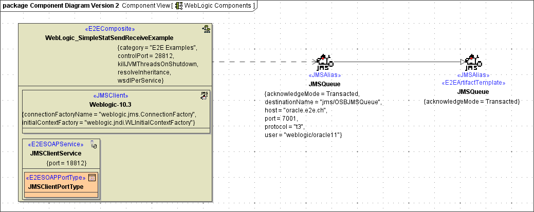
Drag and drop the imported alias onto the component diagram and connect it to the copied alias by drawing a generalization from the copied alias to the imported alias (as shown above).
Repeat this last step, beginning with Defining More Than One Deployment | Creating a Component Diagram Reflecting the Deployment, for every deployment you need.
