Components utilized by E2E services are called backend components or backend services. Their configuration is depicted in the component diagram.
Component Diagram
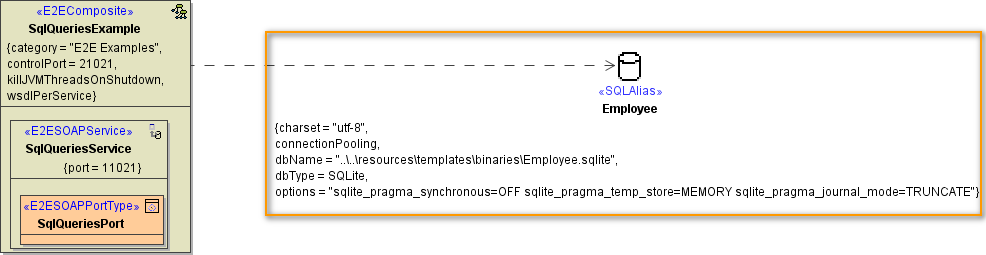
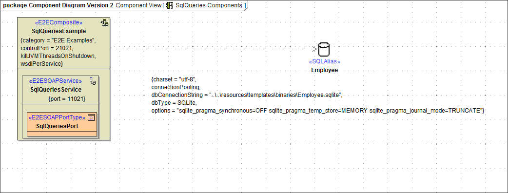
The following component diagram shows an E2E service that uses an SQLite database as backend. This backend is modeled as an alias <<SQLAlias>> Employee connecting to the <<E2EComposite>> SqlQueriesExample. The <<SQLAlias>> contains configuration information of the specific database or more generally speaking: it configures the backend component accessed by the xUML service. SQL databases and other service types accessible by the Bridge are described in the xUML Service Adapters section.
Aliases
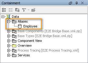
Aliases are stereotyped UML artifacts. Their purpose is to link E2E adapters (defined in the activity diagram) with configuration settings of accessed backend systems. The aliases are defined and configured in the component diagram. For instance, when accessing database systems, the alias is a name that points to the physical database. When the backend system is a Web Service, the alias is a pointer to the port definition. It is recommended to put all aliases into a top level package called Aliases:
Figure: Package Aliases in Containment Tree
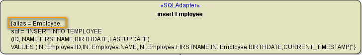
In activity diagrams, only the alias artifacts are assigned to backend adapters. This means that the logical view is separated from the physical view. For example, the following SQL adapter inserts data into the database referred to by the alias Employee.
Figure: Example of an Alias Reference in an Adapter
Creating an Alias
There are two different ways to create a new alias: During the Creation of the Component Diagram in the Components Wizard, or manually on the diagram pane of the component diagram.
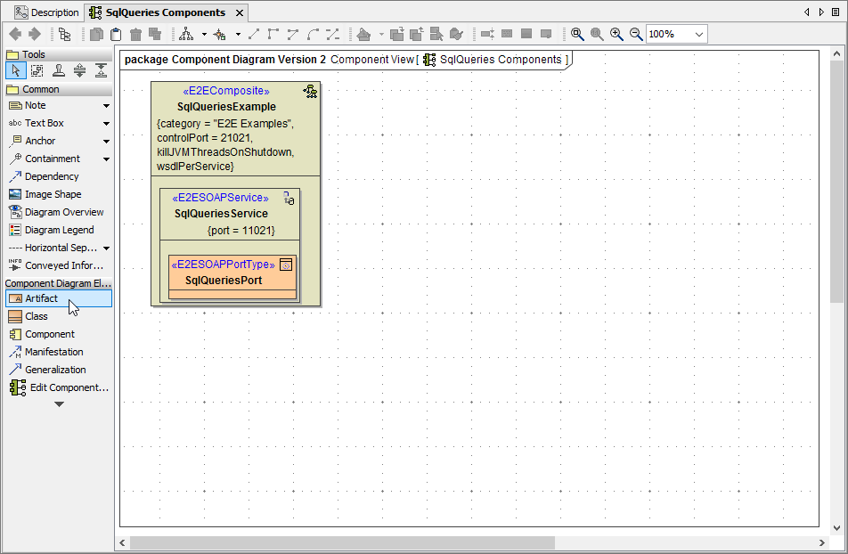 | To create the alias, drag and drop an artifact on the diagram pane. |
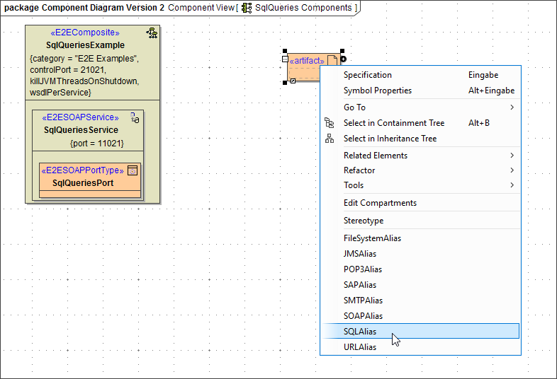 | Right-click the artifact and assign the stereotype corresponding to the alias you need, in our example SQLAlias. |
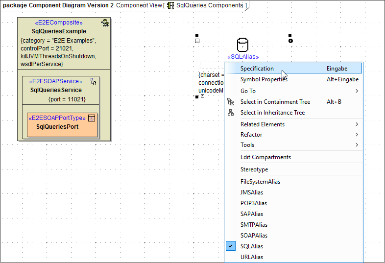 | Open the specification dialog of the new alias. |
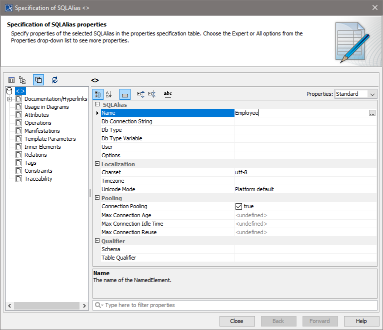 | You are now able to enter all necessary data such as alias name, database type etc. in the specification dialog. Close the window, if you have finished. |
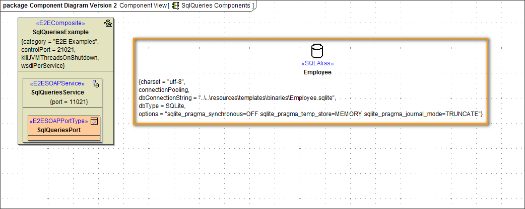 | The alias is displayed on the diagram pane including its specifications. |
 | Finally, you need to connect the <<E2EComposite>> with the <<SQLAlias>> . Select the dependency icon from the diagram toolbar and draw a dependency from the composite to the alias. |
 | The created alias is now connected to the composite. |
Backend Components of E2E Builder Version 5.1
- Deprecated since Builder 6.0
Component Diagram
The following component diagram shows an E2E service that uses an SQLite database as backend. This dependency is modeled as an UML dependency between the <<E2ECompositeDeployment>> SqlQueriesExample and the <<SQLServiceDeployment>> SQLiteArtifact. The <<SQLServiceDeployment>> artifact contains configuration information of the specific database or more generally speaking: it configures the manifested backend component accessed by the xUML service. The backend component itself is modelled as UML component (e.g. <<SQLService>> SQLite). SQL databases and other service types accessible by the Bridge are described in the xUML Service Adapters section.
The dependency between the E2E composite and the backend service contains always a reference to a so-called alias.
Aliases
Aliases are stereotyped UML artifacts (stereotype <<Alias>>). Their purpose is to link E2E adapters (defined in the activity diagram) with configuration settings of accessed backend systems. These settings are defined in the component diagram. For instance, when accessing database systems, the alias is a name that points to the physical database. When the backend system is a Web Service, the alias is a pointer to the port definition. It is recommended to put all aliases into a top level package called Aliases:
In activity diagrams, only the alias artifacts are assigned to backend adapters. This means that the logical view is separated from the physical view. For example, the following SQL adapter inserts data into the database referred to by the alias Employee.
Figure: Example of an Alias Reference in an Adapter
It is important to understand that the alias Employee may refer to dependencies in two different component diagrams in the same model. For example: Suppose you need to handle two different configurations of your service, one for the test and one for the productive environment. In the test environment, SQL statements should be run against an SQLite instance (as depicted in the component diagram above) and in the productive environment against an SQL Server instance. In this case the model contains two component diagrams defining two different composite artifacts one having a dependency to the SQLite database, the other one having a dependency to the SQL Server instance but both referring to the same alias. Both artifacts can be compiled and deployed separately so configuring two different database settings.
However, the activity diagram defining the SQL statement must be drawn only once and has not to be changed when compiling for the one or the other configuration, because at this level only the database alias is used. The information, on which database the statement has to be executed, is only kept in the component diagram.
The configuration information is different for other service types, but the alias mechanism is the same for all services and adapters found in the Add-ons chapter.
Interfaces
Backend service components have interfaces like their frontend service counterparts. Each service interface must be stereotyped. The stereotype of these interfaces depends on the service stereotype. For example, a <<SOAPService>> has <<PortType>> interfaces, a <<SAPRFCService>> has <<SAPRFCModule>> interfaces, etc. (for more examples see section xUML Service Adapters).
Each backend service interface is modeled as UML interface in contrast to interfaces of frontend services that are modeled as classes. The difference derives from the fact that frontend service interfaces are implemented by the modeler whereas backend interfaces are not implemented but just accessed by the modeler.
The interface object stands for the entry point of a backend system, for example the database interface in a RDBMS or the port type interface of a Web Service. The symbol for backend interfaces is similar to the UML symbol for interfaces but instead of having an empty lollipop symbol, the lollipop circle is filled. In the figure below, you find some examples.
Deployment Diagram
Backend component artifacts might be located on server instances different to the current E2E Bridge host. Thus, this information must be added to the model by using a deployment diagram:
Overview
Content Tools