Page History
| Div | ||||||
|---|---|---|---|---|---|---|
| ||||||
|
The following sections are ordered according the steps needed to create a component diagram and describe each creation step in detail.
- Assigning the Diagram Name
- Defining the Composite
- Defining the Frontend Service
- Defining the SOAP Service Interface
- Defining Backend Aliases
- Finishing the Components Wizard
Step 1: Assigning the Diagram Name
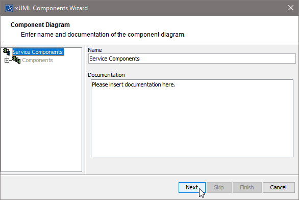
After starting the Components Wizard, the first dialog opens, and you are prompted to enter the name of the component diagram.
| You may use the |
...
...
name suggested or enter a descriptive name. Changing the name will change the name of the top most tree node (marked in blue) in the navigation panel. Click Next to proceed or Cancel to abort. |
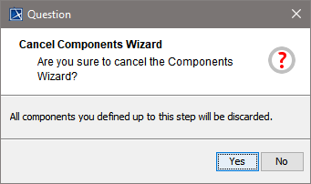
The Components Wizard can be canceled any time.
| After clicking cancel, the Components Wizard prompts for confirmation. |
Step 2: Defining the Composite
...
...
define the service composite. The service composite represents the repository of the Web service and will contain all necessary configuration information.
Clicking Next after
...
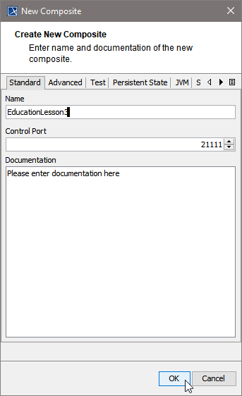
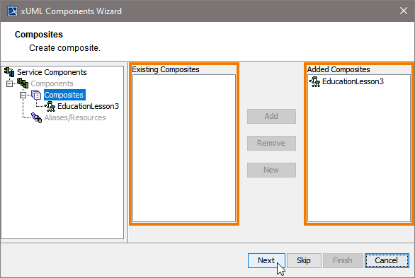
having assigned the diagram name will bring you directly to the following dialog. Create the service composite here.
| Assign a name to the composite. In the field Control Port, enter an unused port number (the value needs to be between 20'000 and 29'999). |
...
| ||
| In case you accidentally clicked the Cancel button |
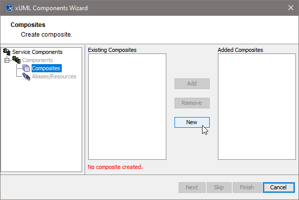
...
| , the Create new Composite window can be re-opened by clicking the New button. |
The Create New Composite dialog contains four more tabs.
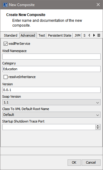
| On the Advanced tab of this dialog, you can |
...
...
...
For more information on these tagged values refer to Frontend Components . | ||||
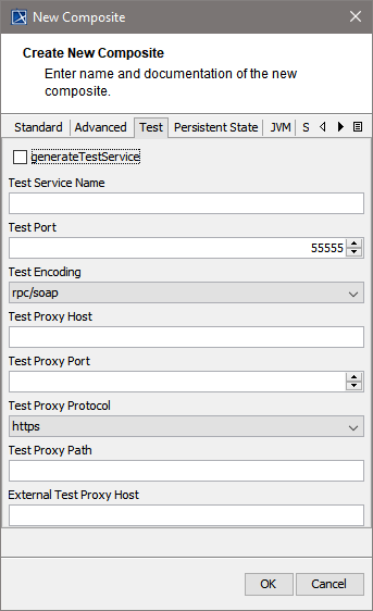
| Specify the test settings here.
|
...
...
...
...
...
...
...
...
...
For more information on testing in general refer to QA Concepts. | ||||||||||
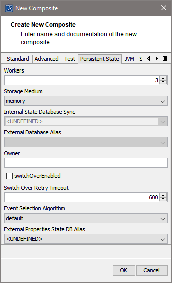
| Using Persistent State features in the xUML service, you can make corresponding adjustments on the Persistent State tab |
...
...
...
For more information Persistent State Components. | |||||||
| Using Java services in the xUML service, you can specify the JVM options here.
|

...
...
...
For more information on Java Components refer to Modeling the Java Components. |
Click OK to proceed.
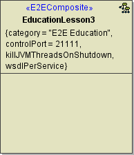
Up to this point, you have defined the xUML service component EducationLesson3.
| In the customization panel, you |
...
...
|
Click Next to proceed.
Step 3: Defining the Frontend Service
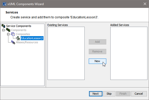
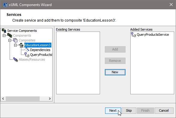
In the next step, you define the frontend service that will be part of the xUML service.
Clicking Next after having defined the composite will bring you directly to the following dialog. Add a frontend service here.
| Select a service type from the list. |
| In other cases, e.g. if you want to add additional services, you can open the above dialog by clicking New on Services level of the tree. |
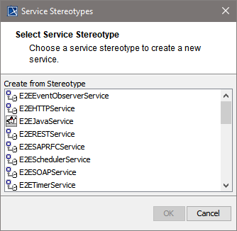
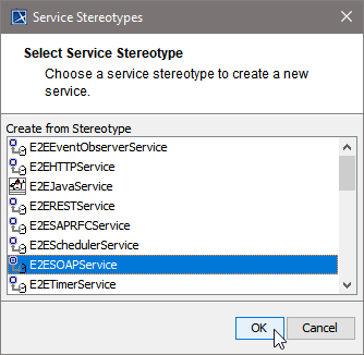
All possible frontend service stereotypes are listed:
|
|
|
|
| This example shows how to define a Web service. Select the service stereotype E2ESOAPService. Proceed with OK. | ||||||||
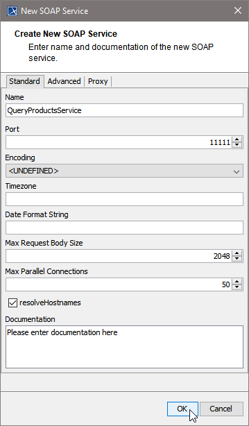
| Now, customize the service artifact.
|
...
...
...
|
The Create New SOAP Service dialog contains two more tabs.
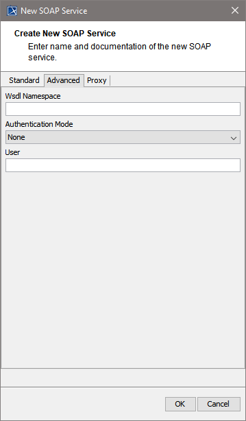
| On the Advanced tab, you can specify the following settings:
|
...
...
...
For detailed information on these tagged values refer to SOAP Service Reference. | ||||||||||
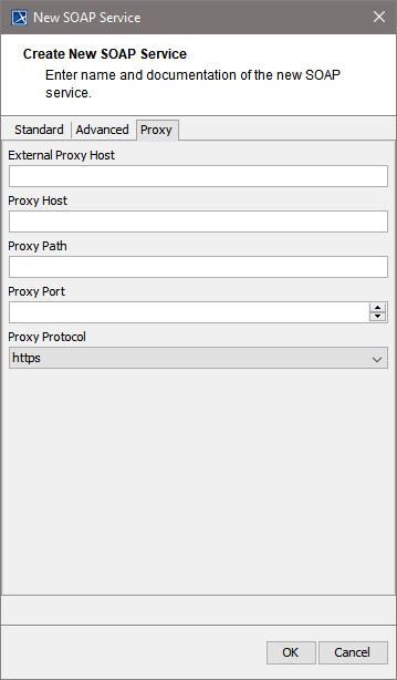 | On the Proxy tab, you can specify the proxy details.
|
...
...
...
...
...
...
...
...
...
...
For detailed information on these tagged values refer to SOAP Service Reference. |
Proceed with OK.
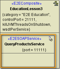
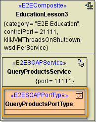
Now, in the component diagram the service component is placed within the service composite component.
| In the customization panel on the right, you will find the new service (e.g. QueryProductsService). |
Click Next to proceed.
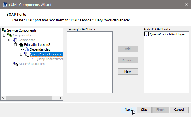
Step 4: Defining the SOAP Service Interface
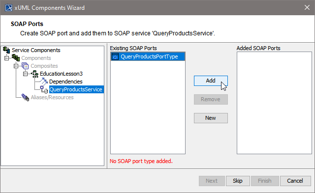
In the next step, you will define the interface of the SOAP service. Through this interface, the Web service is accessible from the outside world.
| The Components Wizard lists all port type classes on the left. Select a port type and |
...
click Add to add the port type to the composite. | |
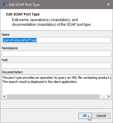
| In the following dialog, assign a name to the port type or use the default name suggested. |
...
Proceed with OK. | |||||
| In the artifact part oft the customization panel, you will find the added port type QueryProductsPortType . As an interface can only be used once in a composite, the port type QueryProductsPortType is not displayed anymore in the SOAP Port Types list on the left. |
...
Click Next to proceed. | |||||
| In the Customized Artifacts part of the tree panel, the xUML service is selected again |
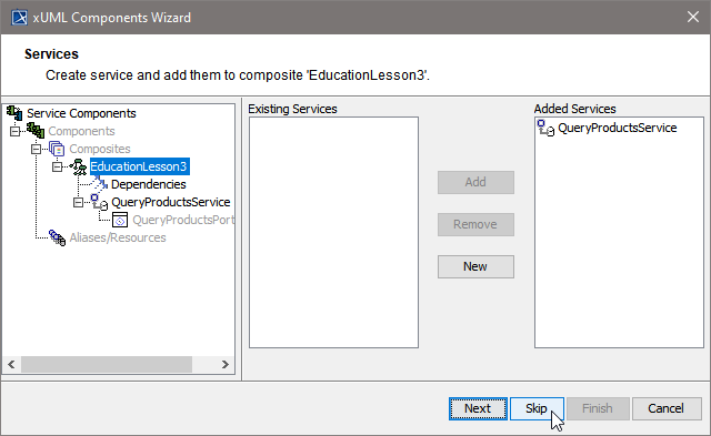
...
to give you the option to define further frontend services (see Defining the Frontend Service). If you do not need any further elements, click Skip. | |
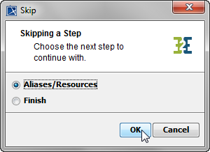 | For definition of Backend Services (Aliases/Resources) see below (Defining Backend Aliases). For Finishing the Components Wizard see Finishing the Components Wizard. |
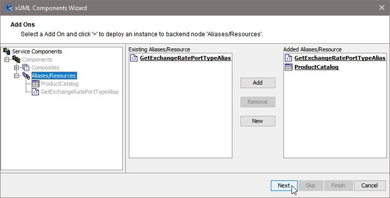
Step 5: Defining Backend Aliases
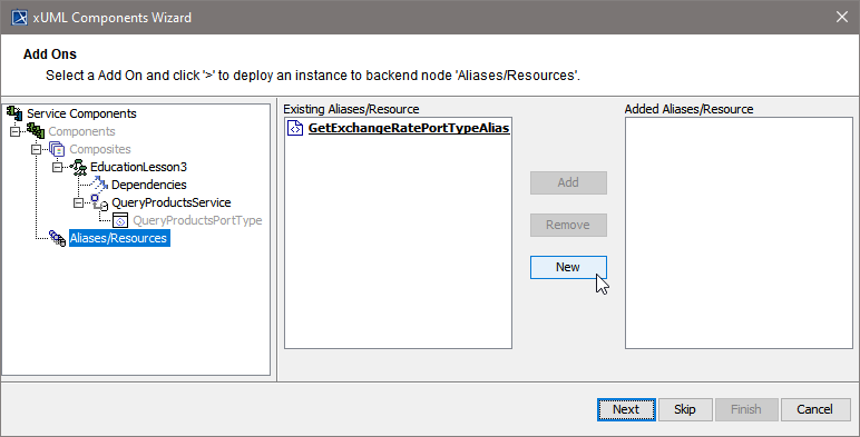
In this step, backend aliases are defined. The Components Wizard provides predefined Backend Components.
| Click New to create a new backend alias ... |
| ...or select an existing alias and |
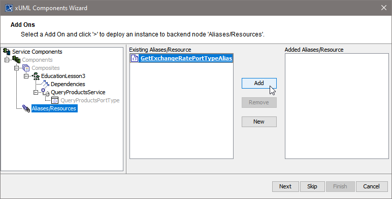
...
| click Add to add it to the component diagram. |
| Anchor | ||||
|---|---|---|---|---|
|
| Backend Aliases | ||||||
|---|---|---|---|---|---|---|
|
| Choose a backend alias stereotype from the list of available stereotypes, e.g. |
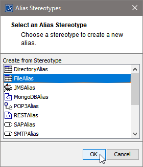
...
FileAlias and click OK. | |
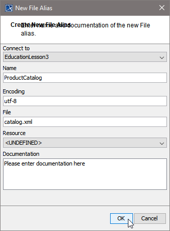
| Assign a name to the alias or leave the default name suggested. Specify File Name and Path, or, if you wanted to read data from an imported resource, select the resource from the Resource drop-down box instead. Click OK. |
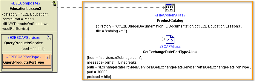
| In right part oft the customization panel, you will find the new file system alias (e.g. ProductCatalog). Click Next. |
Step 6: Finishing the Components Wizard
This is the final step of the Components Wizard
...
...
can select an element node in the tree panel and add further UML elements to the diagram.
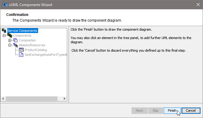
The Components Wizard generates the component diagram. If no errors occurred, it is necessary to save the model. On saving, the deployment data of the Model Compiler gets refreshed and you can proceed with e.g. compiling the model.
| Panel | ||
|---|---|---|
| ||
|
| Panel | ||
|---|---|---|
| ||
Overview
Content Tools