Page History
| Div | ||||||||
|---|---|---|---|---|---|---|---|---|
| ||||||||
|
...
...
...
...
...
...
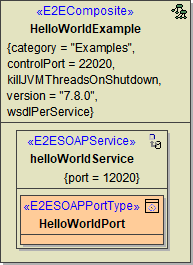
This is the component diagram of the HelloWorldExample.
Each composite manifests itself as repository file after compilation. This means, after compilation the <projectPath>/repository folder contains the repository file HelloWorldExample.rep. Additionally, each of the logical components can be configured by the use of tagged values. This repository belongs to
...
...
...
...
...
...
...
...
...
...
...
...
...
...
...
...
...
...
...
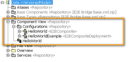
UML models:
Figure: Component View in the Containment Tree
Frontend Components of E2E Builder Version 5.1
| Version | ||
|---|---|---|
| ||
|
...
| title | Click here to read the documentation of the component diagram used in E2E Builder releases before 6.0 ... |
|---|
| Note | ||
|---|---|---|
| ||
Starting with E2E Builder version 6.0 the use of these frontend components is deprecated. |
Component Diagram
The most simple component diagram is depicted below. It contains a <<E2EComposite>> component. This component is the deployment unit of a set of service components. Each <<E2EComposite>> component may contain several services. The different service types are described in the Add-ons chapter. Examples are: SOAP, HTTP, JMS, Java, Timer, Scheduler, SAPRFC, etc. Finally, each service contains at least one class realizing the service. For example, SOAP services contain SOAP port types.
Each of these logical components - composite, service, class - can then be configured by an UML artifact. For instance, each composite manifests itself as repository file after compilation. The filename and some additional parameters can then be configured on the UML artifact manifesting the UML composite component. In the component diagram above, the HelloWorldExample artifact configures the HelloWorld composite. This means, after compilation the <projectPath>/repository folder contains the repository file HelloWorldExample.rep. Additionally, this repository belongs to the category E2EExamples and uses the control port 22020. For further configuration attributes see the table below.
It is important to understand that a composite can be manifested by more than one artifact. This allows to create various deployment instances for each composite. Each composite artifact can then be separately compiled and deployed using the model compiler. For example, the HelloWorldExample composite deployment depicted in the above component diagram is also found in the model compiler view:
Figure: Deployment of Service in Model Compiler
| Note | ||
|---|---|---|
| ||
After deployment, each composite is started as operating system process. More details about this architecture can be found in Bridge Architecture. |
<<E2EComposite>> Attributes
The composite holds the following tagged values:
...
Boolean
...
If true (default=false), each service gets its own WSDL file. Additionally, all XML Schema elements and types having the same namespace are put into one schema file. These schema files are imported into the WSDLs to be shared among them. In this case it is also possible to mix RPC/soap-encoded services with Document/literal services.
...
wsdlNamespace
...
String
...
Target WSDL namespace of the generated WSDL file. Relevant only, if wsdlPerService is false (this is the default).
...
startupActivity
...
Reference to Activity
...
The referenced activity is called while starting up before any other component gets invoked - including timers and schedulers.
...
shutdownActivity
...
Reference to Activity
...
The referenced activity is called when the xUML Runtime is being shutdown.
<<E2ECompositeDeployment>> Attributes
The composite deployment artifact allows to define the following general tagged values:
| Attribute | Type | Description |
|---|---|---|
controlPort | Integer | The control port is used by the E2E Bridge to control the xUML Runtime (see also Service Architecture). The allowed range is 20000 - 29999 |
category | String | The category groups services in the Bridge. |
startupShutdownTracePort | Integer | This port number is used for shadow SOAP port type to trace startup- and shutdown activities. Range is 50000 - 59999. Default = controlPort + 30000. |
Additionally, some tagged values configuring the Persistent State machine can be set as well. These tagged values - externalStateDBAlias, storageMedium, and workers - are described in the Persistent State Components and Deployment chapter.
The component diagrams, the E2E composites, services and all manifesting artifacts are always found in the same place in all E2E UML models:
Deployment Diagram
After having created a component diagram, it is now possible to define a deployment diagram, telling the model compiler where to deploy the compiled repository file. The following deployment diagram shows how to deploy the HelloWorldExample repository to localhost. However, instead of localhost one could use every qualified host name being in the Bridge domain .
All deployment diagrams and deployment instances are found in the same place in all E2E UML models: the so called File View. The name derives from the fact that it describes the deployment of the repository files to machine instances. The File View folder looks like:
...
Overview
Content Tools