Most business processes involve asynchronous processing and require to hold states persistent while communicating via asynchronous messages. In UML, this behavior is supported by state machines. A state machine diagram defines all states a process instance can be in - including the initial and the final state. While in a state, the process instance can receive asynchronous messages via signals, e.g. an abortion signal (MyProcessAbort (6) in the picture below). Changes of state are called transitions.
For each BPMN process that has been modeled with the Designer, the compiled xUML service contains one standard root state machine diagram that supports error handling and compensation as well as history states.
The actual process is integrated to this state machine as a sub state machine (see Executing MyProcess (2)).
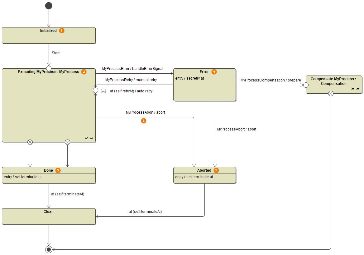
The root state machine features the following states:
| State | Description | Signal Examples | Setting | |
|---|---|---|---|---|
| 1 | Initialized | State Initialized is a temporary state. The process instance passes this state once triggered. | ||
| 2 | Executing | State Executing contains the sub state machine that executes the actual business process. Processes in this state can be aborted by sending the MyProcessAbort signal. |
| |
| 3 | Aborted | When a process has been aborted, it will be transitioned to this state. After having waited the holdTime, the process transitions to state Clean. |
| |
| 4 | Error | If the process triggers an error, it goes to the Error state. |
|
|
| 5 | Done | After the end event of the process has been executed, it is in state Done. After having waited the holdTime, the process transitions to state Clean. |
| |
| Compensate | In future versions of the Designer it will be possible to define process compensation and clean-up tasks. The Compensate and Clean states are designated for that. | |||
| Clean |
| |||
For more details, refer to
Overview
Content Tools