As described on the previous pages, user interfaces can be designed within MagicDraw and then can be facilitated to work as web user interfaces within the browser. Next to modeling the screens, there are many steps to make the UI work, modeling the messages, services, the bindings from the UI elements to the messages and so on. To make it more easy and faster to set up working user interfaces, the UI Importer take care of the initial creation and linking of all needed elements. In fact, the result of the UI Importer are working web user interfaces.
The following pages describe all preconditions which are necessary to set up before an import can be done.
Example File (Builder project Advanced Modeling/UI):
<your example path>\Advanced Modeling\UI\uml\uiImportImplementation.xml |
UI Interaction and UI linking
After the user interfaces are modeled, the Importer has to be told how to import the UI's. There are two preconditions which are essential to make it work, the UI interaction use case diagram and the linking between the designed screens.
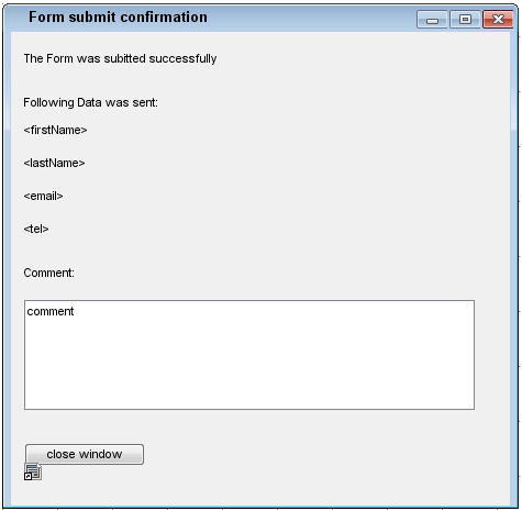
The first step would be to link the user interfaces that when clicking on the UI controls the screens change. In the below example, the simple feedback form submit button is to be linked to the confirmation window and of course vice versa.
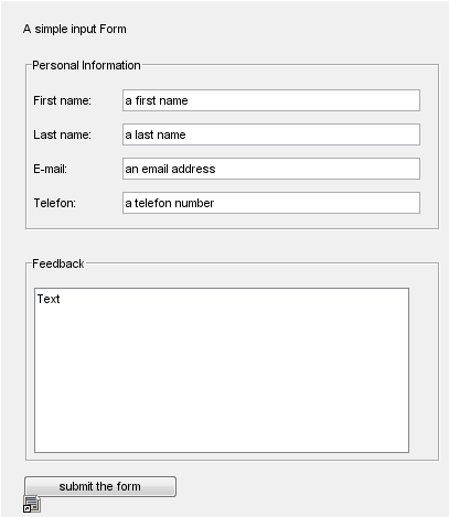
Figure: Linked UI
The linking between the screens will be interpreted as the page flow and after the import will manifest in a state machine.
The next step is to create a UI Interaction use case diagram. As shown in the below figure, this is a use case diagram showing an actor (not interpreted) calling a use case submit feedback. The use case has to be stereotyped with a <<UIInteraction>>. The importer will look for this <<UIInteraction>> and use it as the root and <<UI>> controller. Attached with a dependency you see the Icon of the MagicDraw Interface Modelling Diagram. This in fact is created by dragging the diagram from the containment tree into the use case diagram.
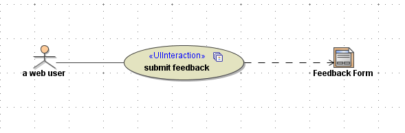
It is also possible to have more than one <<UIInteraction>> within a use case diagram. The import result will have two separate <<UI>> controllers and state machines.
Once this setup is done, the UI prototype is ready to be imported.
Importing the UI
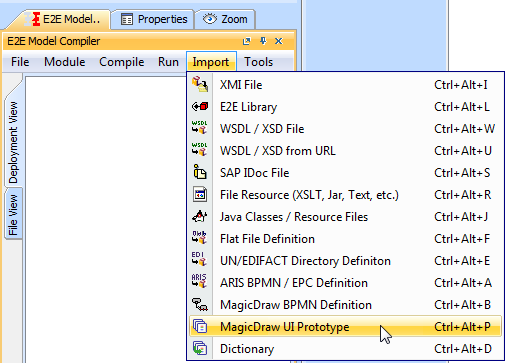
The MagicDraw UI Prototype importer is found in the compiler from within the compiler importer menu as shown in the figure below.
After selecting the MagicDraw UI Prototype importer option a file chooser will appear and ask to select the file containing the UI models. After selecting the model, a dialog appears asking if the import should be done in the existing model or a new one. Choose new model. The new model will hold the user interface services.
Figure: Import type dialog
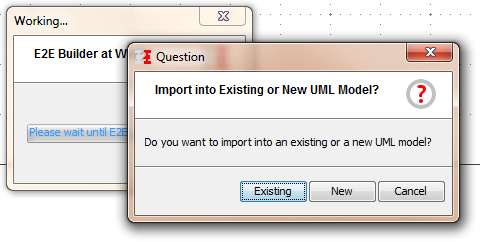
Choose a new file name and save the user interface service in the project of your choice.
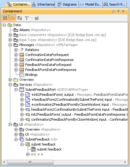
The Generated Service
The MagicDraw UI Prototype importer generates a full working service which, after a component diagram is added, can be run straight away. As you will see, all the user interfaces, the data message classes including the binding to the user interface elements as well as the soap services which handle the data are all created. The next step is to implement the needed logic and finalize user interface specific needs.
On this Page:
Overview
Content Tools