
Remember that component diagrams represent the physical view of the Web service. A component diagram defines how components are wired together to form larger components or software systems. In context of the Bridge you define xUML services that are deployed to an E2E Runtime. The component diagram contains model elements like components, classes, and interfaces.
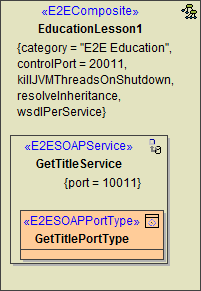
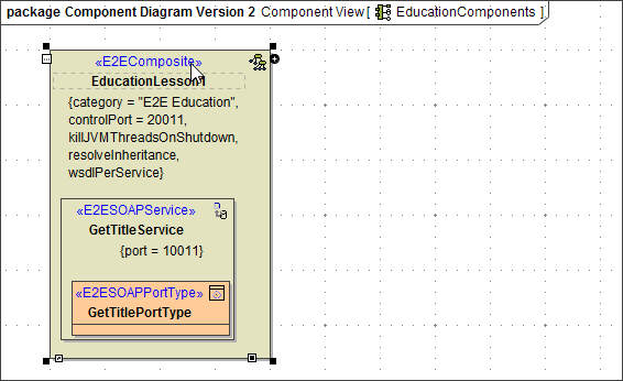
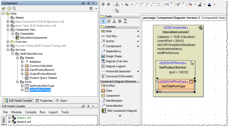
In the picture below you see the initial situation, the component diagram of lesson 1.
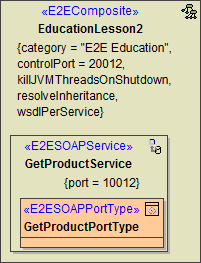
In the next modeling step, you will rework the physical implementation of the Web service. The goal is to provide a second Web service running on the E2E Bridge node instance localhost: The new SOAP service component GetProductService will be specified for the xUML service EducationLesson2.
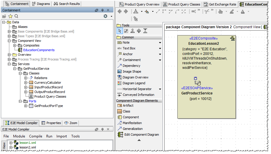
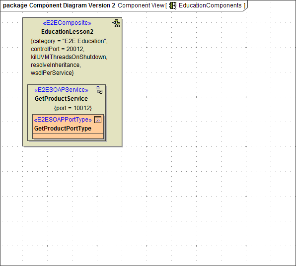
After editing the component diagram, it will look like shown in the following picture.
Reworking the Component Diagram
For reworking the existing component diagram you created in lesson 1, you will do some editing directly in the diagram and use the E2E Components Wizard to create the new port type.
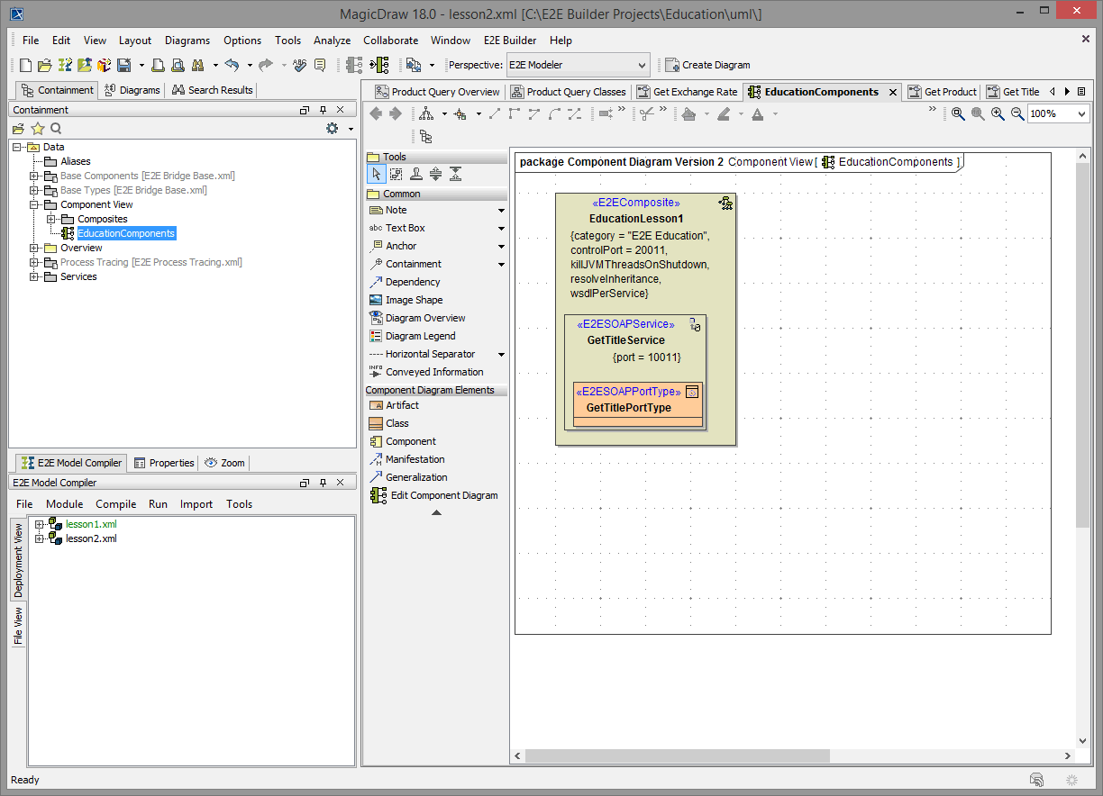
In the containment tree, navigate to Data - Component View - EducationComponents and open the component diagram.
First, you will enter the new names of the xUML service components and change the port number of the SOAP service component, so both services (lesson 1 as well as lesson 2) can be run at the same time.
| Click the <<E2EComposite>> component EducationLesson1 to select the element. | |
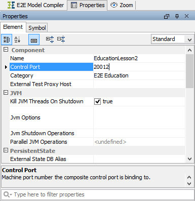
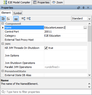 | Switch to the Properties tab in the lower left corner of Magic Draw (where the Model Compiler is situated, too). Change the name of the component to EducationLesson2. | |
| Change the Control Port number to 20012. | |
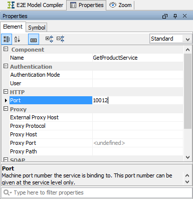
| Select the service component GetTitleService in the diagram pane. In the Properties tab, change it's name to GetProductService and change the Port to 10012. Switch back to the E2E Model Compiler tab. |
Next, you will substitute the old port type GetTitlePortType by the new port type GetProductPortType. First, you will delete the old port type, then insert the new one.
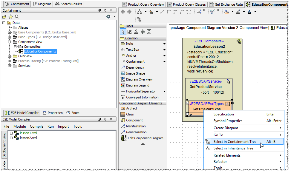
Right-click the port type GetTitlePortType. Select Select in Containment Tree from the context menu.
The containment tree expands automatically and highlights the selected UML element.
Press Del to delete the Component in the containment tree as well as the symbol in the diagram pane.
Note that the Component has been deleted from the diagram pane.
Using the E2E Components Wizard
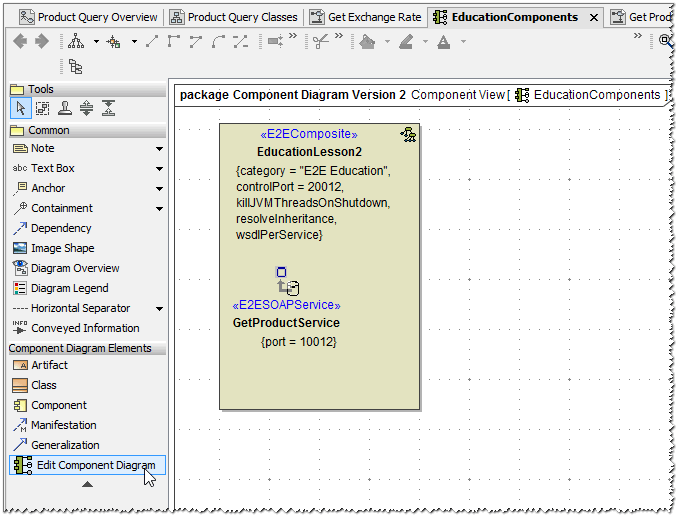
Start the E2E Components Wizard by clicking on the ![]() icon in the diagram toolbar on the left.
icon in the diagram toolbar on the left.
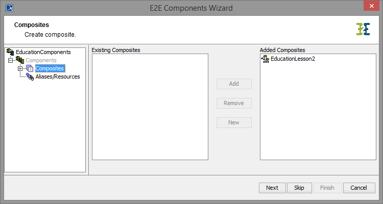
The E2E Components Wizard dialog window opens.
| The wizard displays the service component EducationLesson2. |
| Expand the tree on the left and navigate to the component GetProductService below the Composites node of the tree. |
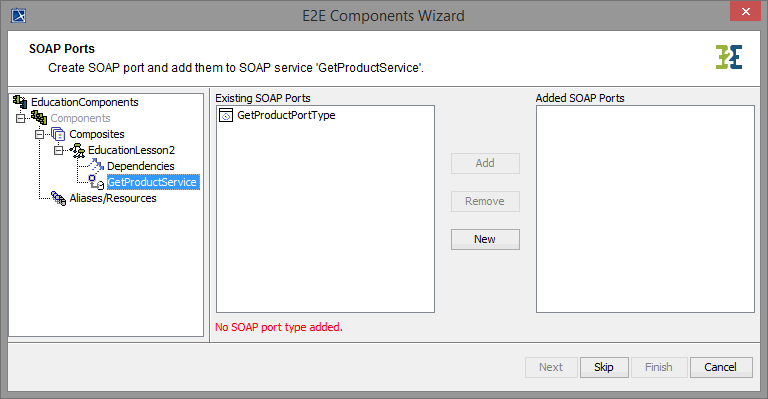
In the SOAP Port Type list, all available port types are listed. As you already deleted GetTitlePortType, GetProductPortType is the only available port type.
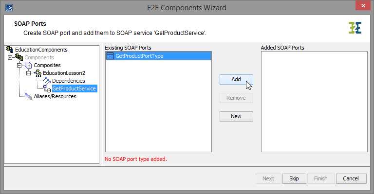
| Select GetProductPortType and click Add to add it to the xUML service. |
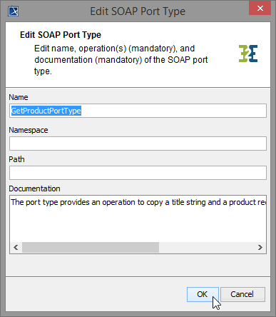
| Click OK for confirmation. |
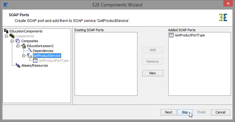
| In the Components part of the tree panel, the service component is selected again, to give you the option to define further frontend services. As you do not need any further elements, click Skip. |
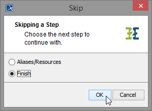
| All necessary components have been defined. As you do not define any backend or proxy in lesson 2, choose the option Finish to continue with the last step. |
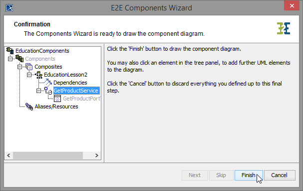
| This is the final step of the Components Wizard. You need to confirm drawing the component diagram. Click Finish. |
The component diagram will be drawn in MagicDraw. The defined components are saved in the package Data / Component View.
The generated component diagram will open.
Save ![]() the UML model.
the UML model.
Now, the xUML service EducationLesson2 can be compiled.

On this Page:
Overview
Content Tools