Activity diagrams can also implement logic that is based on conditions. You can branch a control flow using the Decision element.
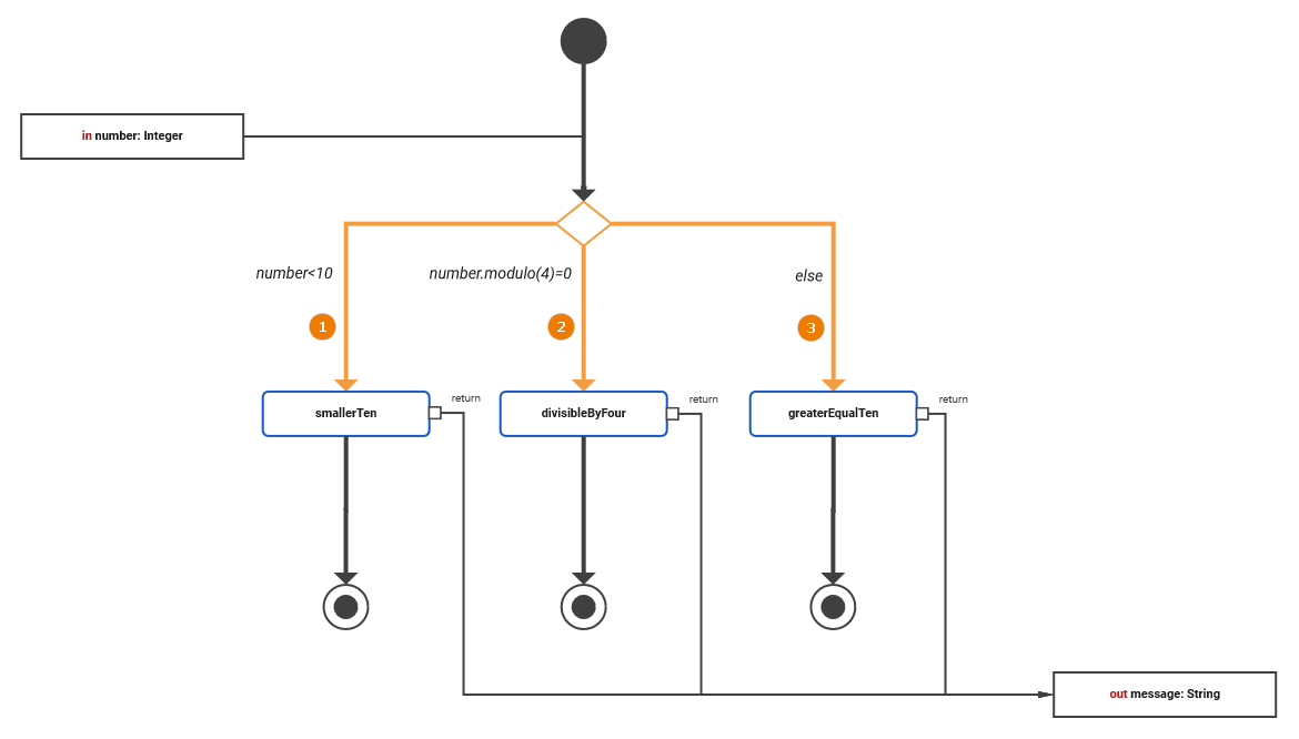
The following example shows how to use decisions in activity diagrams. The user can enter a positive number. The process will then return a message depending on if the number is smaller or greater than 10 and divisible by 4.
The branching conditions of the decision must evaluate to a Boolean value (boolean expression) and be defined on the outgoing control flows of the decision node as a Guard Expression. Page Logical Operators provides a list of all possible logical operators that can be used within a guard expression. You can also use Boolean operators (and, or) as described in Boolean Operators.
In the example above, there are three outgoing control flows:
|
Nr. |
Control Flow |
Condition |
Guard Expression |
|---|---|---|---|
|
(1) |
Decision → smallerTen |
entered number smaller than ten |
|
|
(2) |
Decision → divisibleByFour |
entered number divisible by four |
|
|
(3) |
Decision → greaterEqualTen |
all other cases |
|
The one or more of the control flows contain the actual condition(s) ((1) and (2)). Exactly one control flow must contain an else expression (3): This control flow is followed if all other expressions evaluate to false.
The boolean operators of the xUML Runtime support short-circuiting. This means that the second operand is evaluated only when the result is not fully determined by the first operand.
Adding a Guard Expression
To add a guard expression to a control flow proceed as follows:
-
Select the control flow you want to add a guard expression to from the activity diagram and open the Attributes panel.
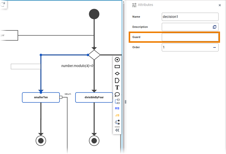
-
Enter a boolean expression into the field Guard Expression.
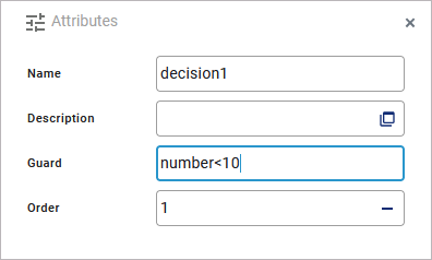
-
The entered expression is also displayed in a box next to the corresponding control flow in the diagram.
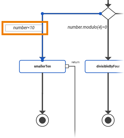
-
When the guard expression box is selected, you can move it any time. Click the box and drag it to the desired position.
-
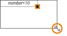
You can resize the guard expression box by clicking the square in the bottom right corner of the element and dragging it.
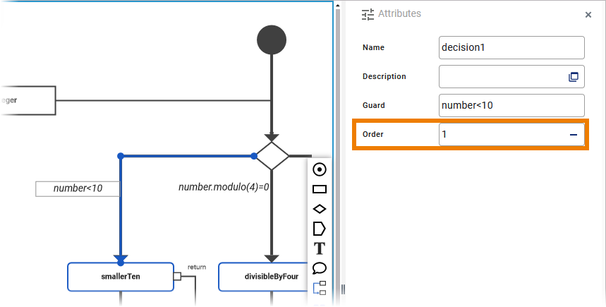
Specifying an Evaluation Order
The order attribute on the decision flow defines the order in which the guards should be evaluated. To add an order to a control flow proceed as follows:
-
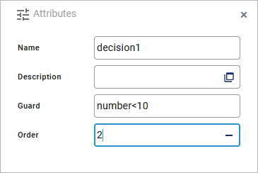
Select the control flow you want to add an order to from the activity diagram and open the Attributes panel.
-
Enter the order number you want to assign to the selected control flow.
Examples
The following table shows some examples regarding the activity diagram above:
|
Example |
Entered Number |
Guard Expression |
Condition |
Result |
|---|---|---|---|---|
|
1 |
7 |
|
|
Branch 1 is followed without evaluating the other two branches |
|
2 |
12 |
|
|
Branch 2 is followed without evaluating the third branch |
|
|
|
|||
|
3 |
14 |
|
|
Branch 3 is followed |
|
|
|
|||
|
|
|
Activity_Decision_Example
Click here to download a simple example model that shows how to use decisions in activity diagrams with Scheer PAS Designer.