User interfaces are modeled with the standard MagicDraw tool set and do not need to have any additional stereotypes applied. However, it makes sense to follow some conventions in organizing the UI elements:
|
|
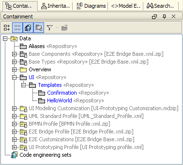
Create a new package structure underneath the root node Data within the Containment tree.
|
|
|
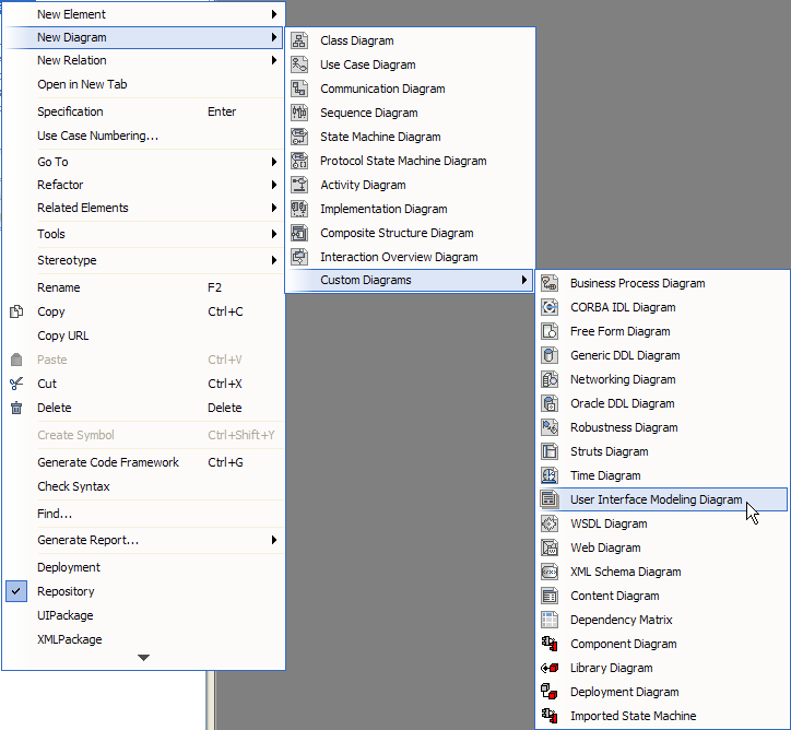
As with Activity or Class Diagrams, user interfaces have a specific diagram type. To create a User Interface Modeling Diagram, right-click on the HelloWorld Repository and select New Diagram > Custom Diagrams > User Interface Modeling Diagram.
|
|
|
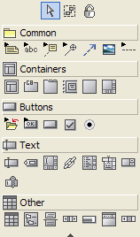
Depending on the diagram type, MagicDraw offers different drawing objects. In this case user interface specific objects appear in the middle tool bar.
|
|
|
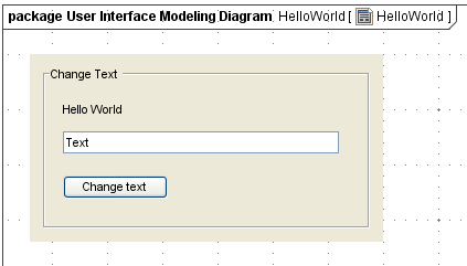
Each screen model is based on a container object on which the elements are placed according to the application design. Container objects can also be nested with additional containers.
|
|
|
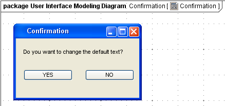
The behavior of a confirmation dialog window is to open up overlaying the main screen. For this reason the Frame () container is used and holds the question Label text () and the YES and NO Button (). |
|
|
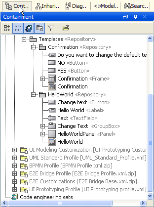
The package structure of the user interface elements should resemble the containment tree structure as shown in the screen shot.
|
UI Navigating (Functional Prototype)
To be able to present user interface prototypes more interactively, MagicDraw offers to hyperlink user interface elements to each other. The hyperlinks are added to an element by clicking on the element you want to assign the link.
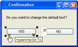
Linking the YES and NO button to the HelloWorld UI diagram allows to jump from the confirmation back to the main screen. On the other side, the Change text button HelloWorld screen has to be linked to the Confirmation UI diagram.

