Page History
When you open the implementation diagram of a mapping operation, a new tab opens, and the mapping diagram is displayed in the mapping editor.
This is where you model your data mapping.
The mapping editor consists of different areas: |
Customizing the Mapping Editor
| You have several options to adjust the mapping editor. When you open the editor for the first time, the default view is displayed:
|
Modeling in the Mapping Editor
When starting with a new mapping diagram, the mapping editor displays a canvas that contains the incoming and outgoing parameters of the mapping operation.

The image above shows the blank mapping diagram of a non-static mapping operation.
On the left side, you can see the mapping source. In this case, the source is the Self context of the related class. If the mapping operation has input parameters, the mapping diagram will also show elements in the Input section of the mapping diagram.
On the right side, you can see the mapping target (section Output). The target is defined by the output parameters of the mapping operation.
Drawing Mapping Relations
Each class property has a connector . Use these connectors to map properties directly from source to target.
Click a connector on the source side of the mapping diagram and drag out a mapping relation.
You can abort this process by pressing the Esc button, or by clicking the right mouse button.
Drag the relation to the connector of the target property.
The color of the target connector indicates whether you can connect the selected properties. Valid connectors are displayed in blue .
Drop the mapping relation on the target connector.
| Tip |
|---|
A source property can be connected to more than one target property. |
If the mapping relation is valid, it is displayed in black, if not, it is displayed in red.
| Tip |
|---|
If invalid mapping relations are not highlighted in red, you may need to enable Show invalid from the mapping toolbar. See Toolbars further below for more details on the mapping toolbar. |
Generally, all mapping relations are arranged automatically in a way that provides the best overview.
If you need to change a mapping relation, take the relation e.g. from the target connector, and move it to another connector.
To delete a mapping relation, click it with the right mouse button, and click on the thrash icon from the context menu (or press the Del button).
Assigning a Literal Value to a Target Property
Click the literal icon from the elements toolbar, and select a property to assign a literal value to (or use drag & drop).
To cancel the procedure, press Esc.
A box appears where you can enter the literal value. Press Enter to save the value.
You can change the value by double-clicking the box and entering a new value.
To delete the literal value, select the box and press the Del key, or select from the context menu.
Refer to the other pages in this chapter for more information on how to model a valid Mapping diagram:
| Children Display |
|---|
Modeling in the
Adding Operations to Mapping Relations
In cases the target and the source type do not match, or you want to perform some other transformation with the mapping, you can add operations to mapping relations.
Drag out the needed operation from the service panel to the mapping operation area - the grey section in the middle of the mapping editor.
| Tip |
|---|
You can also directly use Base Type operations in a mapping diagram. |
Once you have added the operation to the mapping diagram, you can connect the source and target properties to the operation pins.
If you want to create a new mapping operation, you can click the mapping function icon and drag it to the grey mapping operation area.
Mapping Editor
While modeling, some general functionalities help you to browse through your model, and to adjust your working location within the model. Refer to Customizing Editors and Panels for more details.
Toolbars
The mapping editor features a mapping toolbar in the center top of the diagram pane, and an elements toolbar on the right.
| Toolbar | Description | ||||||||||||
|---|---|---|---|---|---|---|---|---|---|---|---|---|---|
| Mapping Toolbar | Use the mapping toolbar to change the appearance of the mapping relations and to jump to the related mapping operation in the service panel.
| ||||||||||||
| Elements Toolbar | The elements toolbar contains all elements that you can create on your mapping diagram.
You can also expand the toolbar by using the |
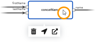
Context Menu of Elements in a Mapping Diagram
Each element of the mapping editor has a context menu that you can select actions from.
| Right click on a mapping element, to open the context menu. Available actions are:
|
Keyboard Shortcuts
Find below a list of all keyboard shortcuts that are available in the mapping editor.
| Table Filter | ||||||||||||||||||||||||
|---|---|---|---|---|---|---|---|---|---|---|---|---|---|---|---|---|---|---|---|---|---|---|---|---|
| ||||||||||||||||||||||||
|
Customizing the Mapping Editor
You can customize the mapping editor and the arrangement of the Designer panels to fit your needs. How to do that is explained in detail on Working with the Designer pp. On that page, you can also find a summary of all available keyboard shortcuts in the Designer, and an explanation of the zooming and scaling features of the editor.
| Panel | ||
|---|---|---|
| ||
|
| Panel | ||
|---|---|---|
|
| Otp | ||||
|---|---|---|---|---|
|
Overview
Content Tools