Page History
Data Mapping is a very common task in the integration business. The Designer offers you a powerful tool to define data mappings directly by drawing object flows between the properties of the related classes.
You can create a mapping diagram by creating a mapping operation on a class. The mapping diagram is based on the data model contained in the Implementation folder. It defines mappings between the data structures defined in this data model. You cannot change the data model in the mapping diagram, all attributes are read-only.
Refer to Modeling Data Structures for more details on how to create a class operation.
Adding a Mapping Operation
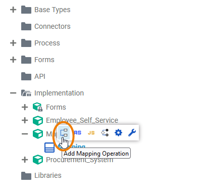
| From the quick actions of a class, select | ||||||||
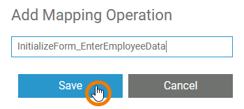
| Enter a name for the operation and click Save.
| ||||||||
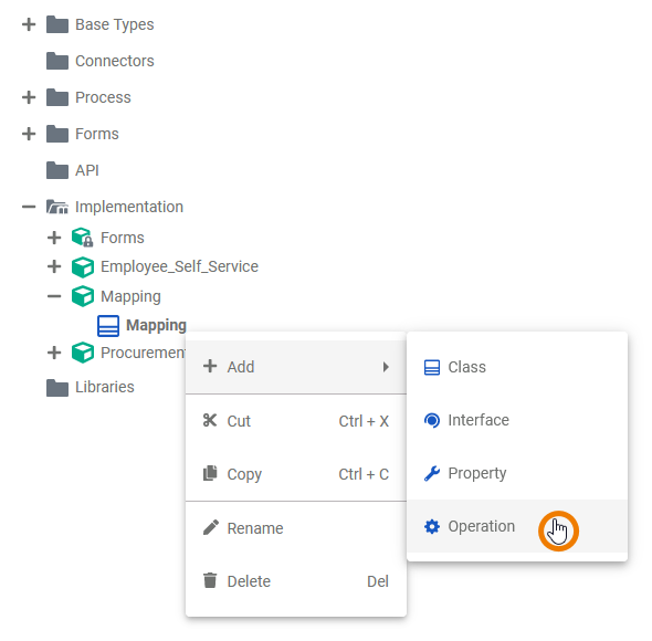
| Alternatively, you can open the context menu of the class and select the option Add Operation. | ||||||||
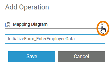
| The dialog Add Operation opens. Select Mapping Diagram from the drop-down list, enter a name for the operation and click Save. | ||||||||
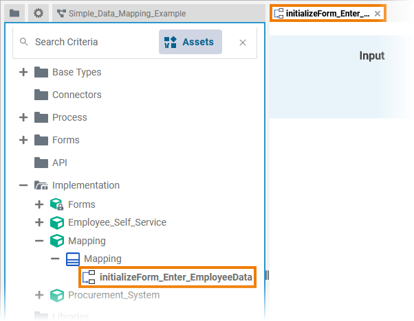
| The new operation has been added to the class. The corresponding mapping diagram opens automatically in a new Designer tab, where you can directly start modeling your mapping.
| ||||||||
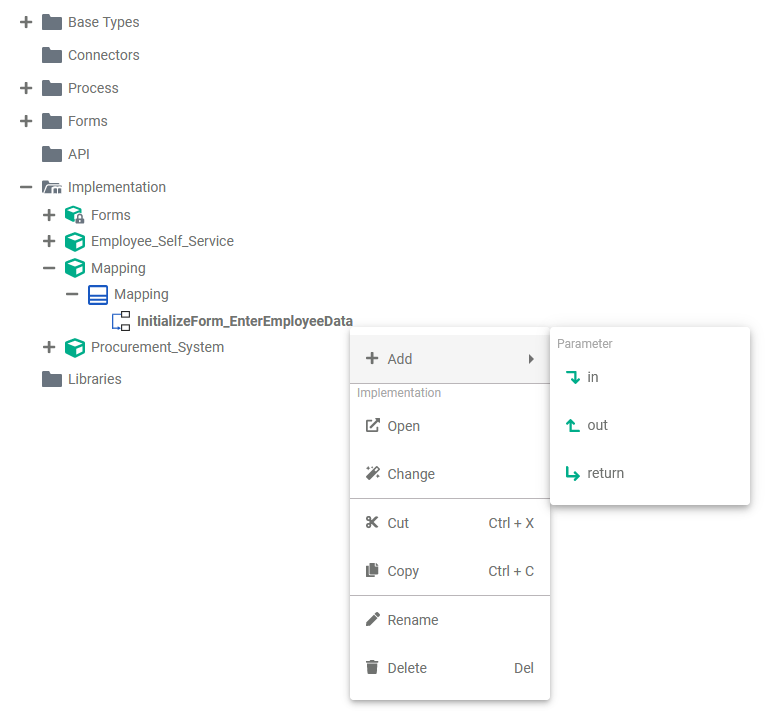
| Once the mapping operation has been created, you can use the quick actions and the context menu to manage it. You can:
|
Refer to Modeling Data Structures for more information on how to create classes and operations.
Mapping Editor Overview
When you create a mapping operation, its corresponding mapping diagram is automatically opened in the Mapping Editor.
If you want to create your own data model within the Designer, you need to create a Service and a BPMN model in the Explorer first. Open the BPMN model to display the BPMN editor where you can find the Service panel. Within the Service panel, the folder Data Model is displayed.
Adding a Data Model
In each Service panel you can find the Data Model folder.
Right click the folder to open the context menu and create a new Package. Within a package, you can create all further elements.
| Tip | ||
|---|---|---|
| ||
Apply the same naming conventions to all your models. This makes reading a model much easier. Go to page Naming Conventions and Containment Tree Organization in the Builder User Guide for an overview on practice-approved naming conventions. |
Data Model Elements
On each element in the Data Model folder you can open a context menu. The context menu contains options to create new elements within the current element, and options to edit the current element.
Package
A package is like a directory for the file system. It is used to group data model elements. Packages can have any depth of nesting: To structure your work, you can create packages within packages.
The Package context menu allows you to edit your package and to create further elements.
| Option | Description |
|---|---|
| Add Package | Add another package within the existing package. |
| Add Class | Add a class within the package. |
| Add Interface | Add an interface within the package. |
| Edit Package | Change the package name. |
| Delete Package | Delete the package. |
| Copy Item | Copy the package to paste it elsewhere in the data model tree. |
| Cut Item | Cut the package to paste it elsewhere in the data model tree. |
| Paste Item | Paste the package elsewhere in the data model tree. Available when Copy Item or Cut Item option have been used before. |
Class
In object-oriented programming, each object belongs to a class. A class is a user defined blueprint from which objects are created. Classes have properties (attributes) and operations (interactions of this class).
The Class context menu allows you to edit your class and to create further elements.
| Option | Description |
|---|---|
| Add Property | Add a property to the class. |
| Add Operation | Add an operation within the class. |
| Edit Class | Change the name of the class. |
| Delete Class | Delete the class. |
| Copy Item | Copy the class to paste it elsewhere in the data model tree. |
| Cut Item | Cut the class to paste it elsewhere in the data model tree. |
| Paste Item | Paste the class elsewhere in the data model tree. Available when Copy Item or Cut Item option have been used before. |
Classes can be created in two ways:
- You can create your own classes using the context menu.
- If you model your own forms within the Designer, each form is added as a class to the Data Model folder in a package Message.
Interface
In contrast to a class, an interface has no implementations. Interfaces are used to define common features of multiple classes in one separate class, and then derive from that class.
The Interface context menu allows you to edit your interface and to create further elements.
| Option | Description |
|---|---|
| Add Operation | Add an operation within the interface. |
| Edit Interface | Change the name of the interface. |
| Delete Interface | Delete the interface. |
| Copy Item | Copy the interface to paste it elsewhere in the data model tree. |
| Cut Item | Cut the interface to paste it elsewhere in the data model tree. |
| Paste Item | Paste the interface elsewhere in the data model tree. Available when Copy Item or Cut Item option have been used before. |
Property
Properties are values that are included within a class. Properties always have a type.
The Property context menu allows you to edit your property. It is not possible to create further elements within a property.
| Option | Description |
|---|---|
| Edit Property | Change the name of the property. |
| Delete Property | Delete the property. |
| Copy Item | Copy the property to paste it elsewhere in the data model tree. |
| Cut Item | Cut the property to paste it elsewhere in the data model tree. |
Properties are created in two ways:
- You can create your own properties using the context menu.
- If you model your own forms within the Designer, each form is added as a class and form elements are added as properties of these classes in the Data Model folder in package Message.
Operation
An operation is an action that is carried out to accomplish a given job. Operations can be defined on classes or interfaces. There are several possibilities to implement an operationsss.
The Operation context menu allows you to edit your operation and to create further elements.
| Option | Description |
|---|---|
| Add Parameter | Add a parameter to the operation. |
| Create Implementation | You can choose between two different types of implementation for your class operations:
If an implementation has been added for an operation, the operation icon changes: |
| Edit Operation | Change the name of the operation. |
| Delete Operation | Delete the operation. |
| Copy Item | Copy the operation to paste it elsewhere in the data model tree. |
| Cut Item | Cut the operation to paste it elsewhere in the data model tree. |
| Paste Item | Paste the operation elsewhere in the data model tree. Available when Copy Item or Cut Item option have been used before. |
Parameter
Each operation can have parameters that define the input and output objects. Operation parameters may not only be of complex types but also of base types.
The Parameter context menu allows you to edit your parameter. It is not possible to create further elements within a parameter.
| Option | Description | ||
|---|---|---|---|
| Edit Parameter | Change the name of the parameter.
| ||
| Move Parameter up | Change the order of parameters. | ||
| Delete Parameter | Delete the parameter. | ||
| Copy Item | Copy the parameter to paste it elsewhere in the data model tree. | ||
| Cut Item | Cut the property to paste it elsewhere in the data model tree. |
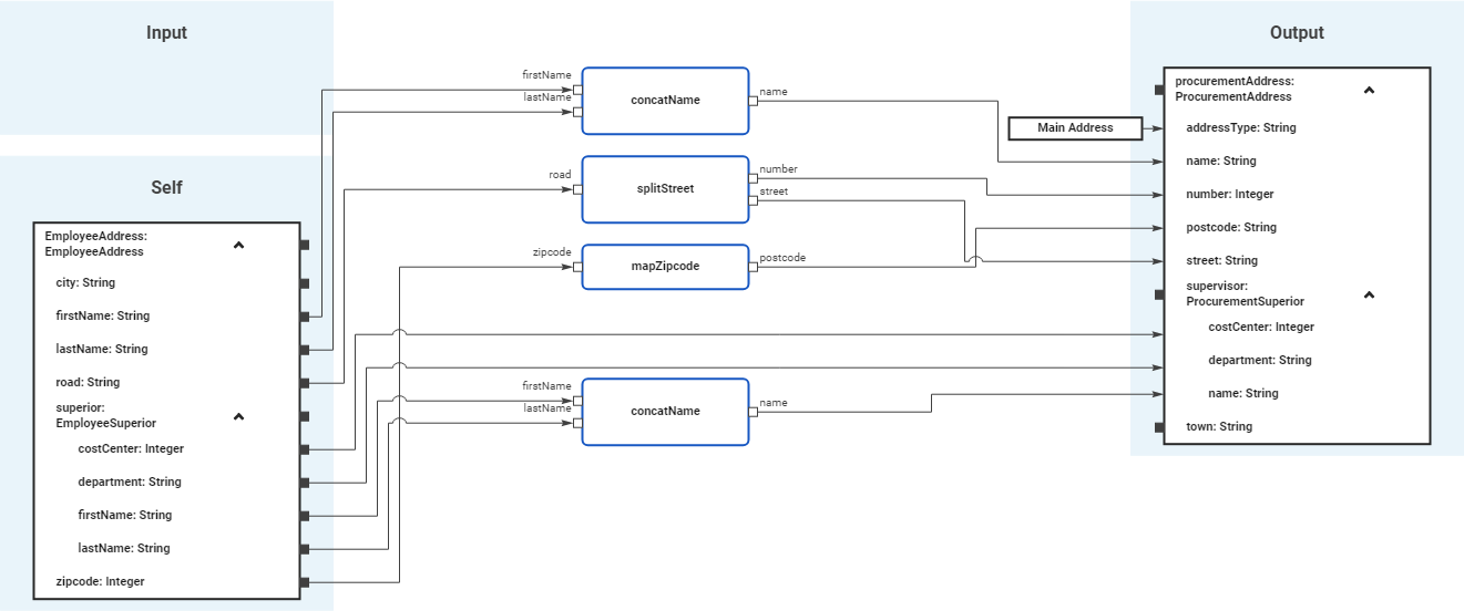
Using the Mapping Editor
When you create a new mapping diagram, it is automatically opened in the Mapping Editor:

Use the various functionalities of the BPMN Mapping Editor to design create your BPMN modelmapping diagram:
| Name | Description | ||||||||
|---|---|---|---|---|---|---|---|---|---|
| 1 | Mapping Editor | The Mapping Editor mapping editor is where you design draw your formdata mappings. Go to page Working with the Mapping Editor for detailed information about the features of the Mapping Editoreditor. | |||||||
| 2 | Elements Toolbar | The elements toolbar contains all elements that you can create in the Mapping Editormapping editor. Go to page Working with the Mapping Editor for further details about the usage of the toolbar. | |||||||
| 3 | Model Toolbar | The model toolbar of the mapping editor offers the following:
| |||||||
| 4 | Designer Panels | In the Mapping Editormapping editor, the following panels assist you during modeling:
| |||||||
Attributes of a Mapping Operation
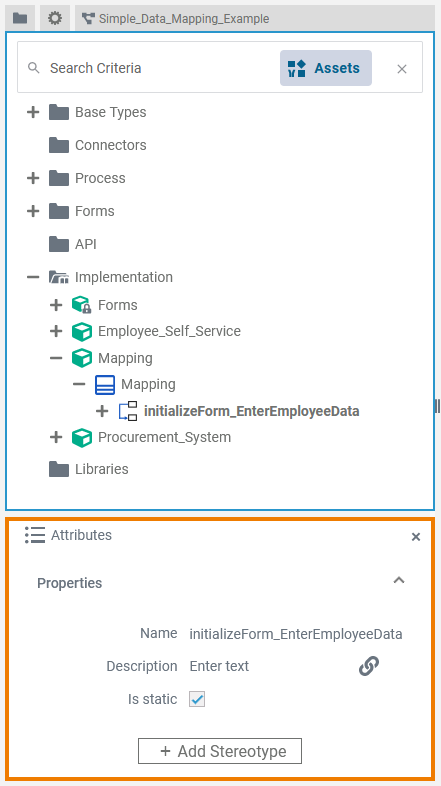
| Select a mapping operation in the Implementation folder of the Service panel to display its attributes in the Attributes panel. You can also edit them there. Mapping operations have the following attributes:
| ||||||||||||||||||||||
Attributes of a Mapping Diagram
| When you click on the diagram pane in the Mapping Editor, the attributes of the current mapping diagram are displayed in the Attributes panel. All attributes are read-only and cannot be edited there. |
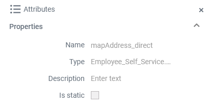
Mapping diagrams have the following attributes:
| Attribute | Description | Possible Values / Example | |
|---|---|---|---|
| Name | Displays the name of the current mapping diagram. | mapAddress_direct | |
| Type | Path within the implementation folder where the corresponding mapping operation resides. | Employee_Self_Service.EmployeeAddress | |
| Description | Description of the corresponding mapping operation for documentation purposes. | ||
| Is static | Displays if the operation is static (default) or not (see Attributes of a Mapping Operation). For more information, also refer to Adding Operation Calls. | true | The mapping operation is static (default) and can be used outside the context of the related class. |
| false | The mapping operation is non-static and needs a self object as an input. | ||
| Panel | ||
|---|---|---|
| ||
|
| Multiexcerpt include | ||||||
|---|---|---|---|---|---|---|
|
Go to chapter Mapping Data Structures in the PAS Designer Developer Guide for more mapping examples.
| Panel | ||
|---|---|---|
|
| Otp | ||||
|---|---|---|---|---|
|
Overview
Content Tools