Page History
| Multiexcerpt | |||||
|---|---|---|---|---|---|
| |||||
The first step of requirement analysis is to establish the business case for the system and to delimit the projects scope. You need to identify all external entities, with which the system will interact (actors). The nature of this interaction is defined at a high level (use cases). Below you find the steps of the design process:
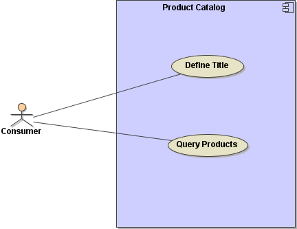
After completing and saving the UML model, it is stored in XMI format. After compilation of the UML model, the xUML service repository is deployed to a physical E2E Bridge node instance. For each deployed xUML service, a Bridge process will be created at startup. The service is ready to be used by client applications, for instance via the SOAP interface in case of a Web service. The next chapters describe the UML models created during the development process. Use CasesThe use case view models the functionality of the system as perceived by outside users, which are called actors. A use case is a coherent unit of functionality expressed as a transaction among actors and the system. The purpose of the use case view is to list the actors and use cases, in order to show which actors participate in each use case.
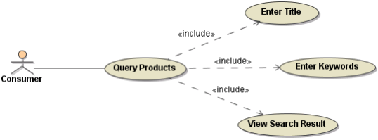
Use cases can also be described in various levels of detail. They can be factored and described in terms of other, simpler use cases. A use case is implemented as collaboration in the interaction view (e.g. sequence diagrams).
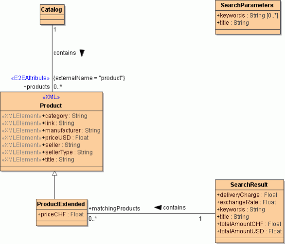
ClassesA class is the description of a concept from the application domain or the application solution. It is a static view, which is displayed in a class diagram. Classes are drawn as rectangles and contain attributes and operations. A class can also be used with other diagrams.
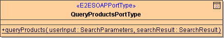
Web Service InterfaceA port type is the interface of a Web service. In this context, an interface describes a class with operations that are accessible from the outside world via SOAP calls.
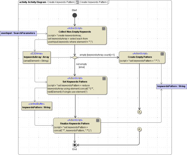
ActivitiesActivities are helpful in understanding the high-level execution behavior of a system. The behavior is defined in activity diagrams, which contain action nodes and control flows that show sequence dependencies. An action node is drawn as a rectangle with round corners and represents an activity: a workflow step or the execution of an operation. Control flows are drawn as arrows between the action nodes. They can have guards with logical expressions that evaluate to true or false. A decision node is displayed using a rhombus symbol. Depending on which guard evaluates to true, the flow follows the corresponding transition. Activity diagrams are also useful for modeling parallel processes because they show, at which point they need to be synchronized.
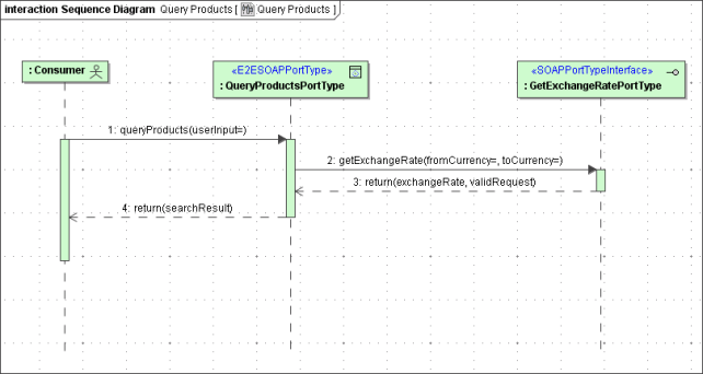
SequencesA sequence diagram shows a set of messages arranged in a time sequence. Each classifier role is shown as a lifeline – that is, a vertical line that represents the role over time through the entire interaction. Messages are shown as arrows between lifelines. A sequence diagram can show a scenario, which is an individual history of a transaction. One use of a sequence diagram is to show the behavior sequence of a use case. When the behavior is implemented, each message on a sequence diagram corresponds to an operation on a class or an event trigger on a transition in a state machine.
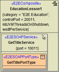
ComponentsThe component view models the components in a system, or the software units from which the application is constructed. In the component diagram, you define the model elements of a service like components, classes, and interfaces, which are manifested in artifacts. An artifact defined by the modeler represents a concrete element in the physical world. It is the specification of a physical piece of information that is produced by the E2E Model Compiler. The most important artifact in the context of the Bridge is the repository file generated by the Model Compiler. The repository can be deployed to an E2E Bridge. |

moveon
Link
LinkText Creating a Web Service Otp Floating false
| Panel |
|---|
| Panel | ||
|---|---|---|
| ||
|
Overview
Content Tools