The following UML elements are supported for modeling activities in the Designer:
| Page | Element | Description |
|---|---|---|
| Throw Exception |
|
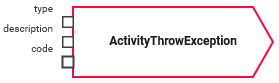
Throw Exceptions can be used to make the xUML Runtime throw a user-defined exception. Type, code and description of the exception can be defined via input pins. |
| Comment |
|
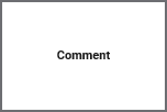
You can add a Comment to the activity diagram to make your diagram easier to read and to provide additional information. This has no effect on the execution, it is just for documenting purposes. |
| Object Flow |
|
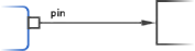
The Object Flow connects pins to local variables and vice versa. |
| Initial Node |

|
The Initial Node marks the start of an activity diagram. An activity diagram must have one (and only one) initial node. |
| Control Flow |
|
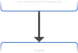
The Control Flow connects the initial node of an activity diagram with the final node. In between, you can add several action nodes. |
| Decision |

|
A Decision can be used to split the control flow of an activity diagram. |
| Local Variable |
|
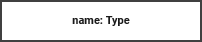
Local Variables are represented by an object node in the activity diagram. It can be used to forward data from one action node to another. |
| Operation |

|
An Operation is represented by an action node in the activity diagram. Operations are used to add actions to an activity diagram. They have exactly one incoming and one outgoing control flow. |
| Literal |
|
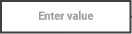
Literals reflect Local Constants. You can use them to provide a literal value within an activity diagram. |
| Final Node |

|
The Final Node marks the end of an activity diagram. An activity diagram must have at least one final node but can have multiple. |
Related Content
Related Pages: