Modeling integration scenarios frequently involves asynchronous processes. For example, a purchase order process is initialized by the first order. Then, the user adds new items until the process is closed by receiving the payment and sending the goods to the customer. All activities involved in this process (such processes are also known as long running transactions) may be separated by days or even weeks making it necessary to hold the states of such a purchase order persistent.
Many business processes require to hold states persistent and to communicate via asynchronous messages. Therefore, integration services being part of such processes must support stateful behavior. In UML, state machine diagrams and signals model such behavior in a very concise and elegant way. The state machine diagram defines all states an object can be in - including the initial and the final state. Being in the final state means most frequently the destruction of the object. Signals model asynchronous messages received by the object. These signals trigger the transitions between object states.
The following sections explain how to model objects having persistent states. Such objects are called persistent state objects. A persistent state object is an instance of a <<PersistentState>> class. Such objects are required to be in exactly one persistent state. After creating such an object, only events trigger state changes. The Bridge supports signal and time events. Signal events occur when receiving a signal - that is, an asynchronous message. Time events trigger state change after the object has been in a state for a given period. Time events are also defined in state machine diagrams.
The following diagrams model persistent state objects:
-
Class diagrams. They show the structural relationship between <<PersistentState>> classes and other model elements such as signals and other classes (see chapters Persistent State Classes and Persistent State Signals).
-
State machine diagrams. Each state machine diagram belongs to a <<PersistentState>> class. It defines the behavior of this class and the life cycle of its objects (see chapter State Machine Diagrams).
The terms state machine diagram, state diagram and state chart are used synonymously.
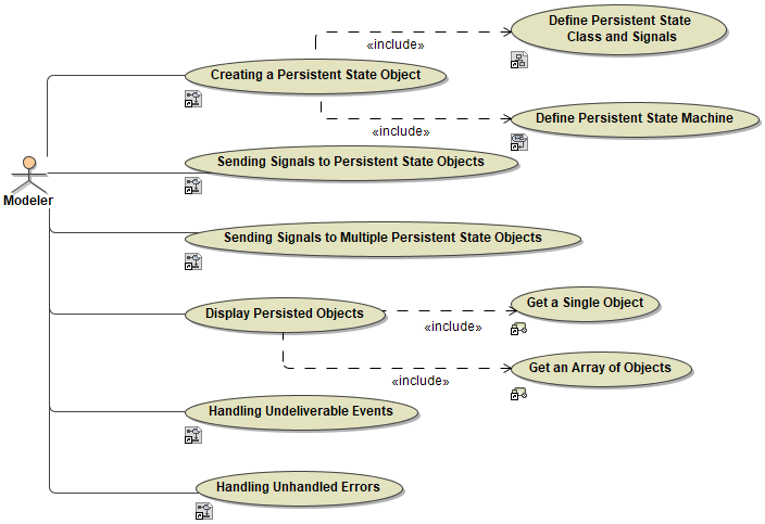
Besides describing the life cycle of stateful objects, the persistent state framework also provides mechanisms to access and manipulate such objects. The most basic use cases in working with persistent state objects are:
Figure: Basic Ways of Modeling, Creating, and Using Persistent State Objects

The following chapters will further elaborate these use cases:
Example File (Builder project Advanced Modeling/PState):
<your example path>\Advanced Modeling\PState\uml\pstatePurchaseOrder.xml
However, besides the most basic use cases covered in the pstatePurchaseOrder.xml example, there are many other useful features such as
-
Conversations: How to communicate with state machines synchronously
-
Composite and Submachine states: How to build more complicated nested state machines
-
History states: How to re-enter a composite state at the same sub-state it has been left
