State Machine Diagrams
A state machine diagram that is assigned to a <<PersistentState>> class governs its behavior. This state machine diagram defines all persistent states of the object and transitions between the states. These states are persistent, that is, they are independent of the life-cycle of the xUML Runtime.
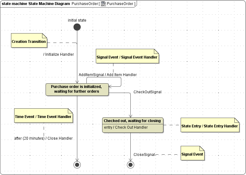
Below an example of the state machine diagram of Purchase Order is shown. An object of this class can only be in the two states Initialized and Checked out. Depending on signals and time-outs, the object changes its state or is ultimately destroyed.
Figure: State Machine Diagram of a Purchase Order

Find a detailed descriptions of all states and transitions and their characteristics on:
